
A device for detecting the strength of building materials

A technology for building materials and strength detection, applied in the field of detection, can solve problems such as poor detection and characterization capabilities, and achieve the effects of increasing detection capabilities, improving continuity, and realizing sequential detection.

Active Publication Date: 2022-02-11
邳州市耿联军机械制造厂
View PDF9 Cites 2 Cited by
  • Summary
  • Abstract
  • Description
  • Claims
  • Application Information

AI Technical Summary

Problems solved by technology

[0003] At present, in the quality inspection of building materials, for the inspection of concrete strength inspection and mortar strength inspection, the method of laboratory inspection is mostly used for inspection. Taking concrete strength inspection as an example, the inspection samples generally have margins. The rear part is not the subject of force, so the general detection and characterization ability is poor

Method used


Image

  • A device for detecting the strength of building materials
  • A device for detecting the strength of building materials
  • A device for detecting the strength of building materials

Examples


Embodiment 1

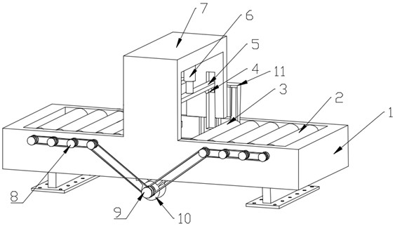
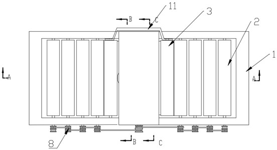
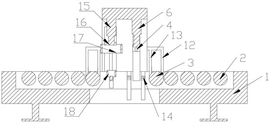
[0033] refer to Figure 1~Figure 3 In this embodiment, a building material strength detection device is proposed, which is used for strength detection of building panels, and the building material strength detection device includes: a workbench 1, a support frame 7, a first drive telescopic rod 6 and The second drives the telescopic rod 15 .

[0034] The workbench 1 is provided with support legs at the bottom, and the bottom of the support legs is fixedly connected with a backing plate, and the support legs support the workbench 1 to a specified height, and the setting of the backing plates increases the stability of the support legs. A through hole is provided on the backing plate, and the setting of the through hole is convenient for fixing the supporting legs by screws, thereby fixing the device. A support frame 7 is fixedly arranged on the workbench 1 .

[0035] The second installation frame 16 and the lifting frame 22 are relatively liftable and arranged inside the supp...

Embodiment 2

[0045] Two groups of transmission rollers 2 are arranged on the workbench 1 for relative rotation, and each group of transmission rollers 2 is provided with several. Drive pulley 8, connect by belt between each driven pulley 8, motor 10 is installed on the workbench 1, the coaxial output shaft of motor 10 is fixedly connected with drive pulley 9, and drive pulley 9 is connected with driven pulley 8 by belt, In this way, the transmission of building materials can be completed. When the conveying roller 2 at one end conveys the building materials to the feeding roller 3, the conveying roller 2 stops conveying. The material is delivered. The feeding roller 3 and the conveying roller 2 are provided with a rubber layer, and the conveying roller 2 and the driven pulley 8 are unidirectionally driven. When the feeding roller 3 conveys intermittently, the conveying roller 2 rolls to avoid hindering the building materials. Thereby, the smoothness of the transmission of the feed drum 3 ...


PUM


Abstract

The invention relates to the field of detection technology, and discloses a building material strength detection device, comprising: a workbench; a second mounting frame and a lifting frame, which are relatively liftable and arranged inside the support frame, between the second mounting frame and the lifting frame Connected by a symmetrical transmission structure, a pressing ring and an upper top ring are fixedly provided on opposite surfaces of the second mounting frame and the lifting frame respectively. The second driving telescopic rod is fixedly installed on the supporting frame and connected with the second mounting frame. The first mounting frame and the connecting rod are relatively liftable and arranged inside the support frame. The first mounting frame and the connecting rod are connected by a symmetrical transmission structure. The two ends of the bottom of the first mounting frame are rotated and provided with pressing rollers. On the connecting rod The flush turning setup has two upper top rollers. The first driving telescopic rod is connected with the first installation frame. Feed drum, rotating set has two. The first pressure sensor component, the second pressure sensor component and the controller. The invention has strong detection ability through the detection of the middle part and the edge part.

Description

technical field [0001] The invention relates to the technical field of detection, in particular to a device for detecting strength of building materials. Background technique [0002] With the development of technology and the increase of population, more and more houses are needed. Building materials can be divided into structural materials, decorative materials and some special materials, among which structural building materials include wood, bamboo, stone, cement, concrete, metal, bricks, ceramics, glass, engineering plastics, composite materials, etc. What kind of structural building materials need to complete a series of quality tests before they are put into use, including strength testing of building materials, and strength testing requires the use of specific strength testing equipment. [0003] At present, in the quality inspection of building materials, for the inspection of concrete strength inspection and mortar strength inspection, the method of laboratory ins...

Claims


Application Information

Patent Timeline
Patent Type & Authority Patents(China)
IPC IPC(8): G01N3/02G01N3/08
CPCG01N3/02G01N3/08G01N2203/0003G01N2203/0019
Inventor 孙振耿联军耿磊
Owner 邳州市耿联军机械制造厂
Learn More