Air conditioning system
An air-conditioning system, air-conditioning technology, applied in the direction of air-conditioning system, ventilation system, heating and ventilation control system, etc.
- Summary
- Abstract
- Description
- Claims
- Application Information
AI Technical Summary
Problems solved by technology
Method used
Image
Examples
no. 1 approach >
[0063] (1) Overall structure
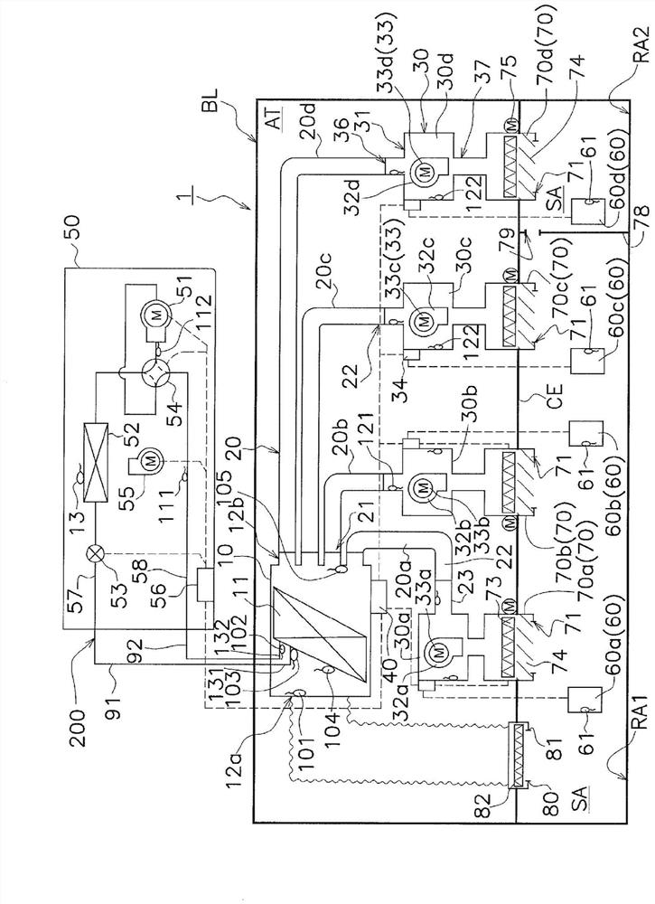
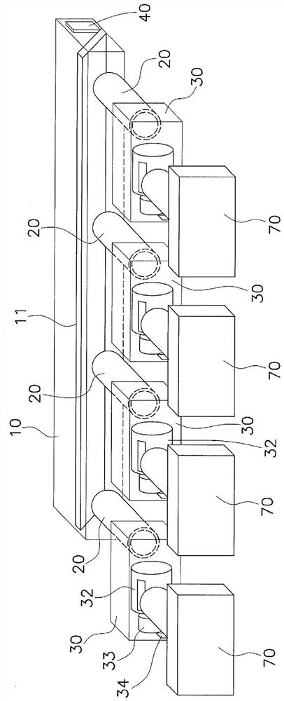
[0064] figure 1 The shown air conditioning system 1 is a system for supplying conditioned air to an air-conditioning target space SA. In the air-conditioning target space SA, there are rooms RA1, RA2, etc. in the building BL. The rooms RA1 , RA2 are separated by a partition wall 78 . Here, the case where the air-conditioning target space SA is two rooms RA1 and RA2 will be described, but the air-conditioning system 1 can cope with various sizes, various shapes, and various numbers of rooms. The air-conditioning target space SA to which the air-conditioning system 1 supplies conditioned air is preferably surrounded by walls (front and back, up and down, left and right) like the rooms RA1 and RA2. In addition, the air-conditioning target space SA is not limited to the rooms RA1 and RA2, and may be, for example, a corridor, stairs, and an entrance. The air-conditioning target space SA may be, for example, one space such as a lobby, or may be a p...
no. 2 approach
[0235] (6) Overall structure
[0236] The aspect in which the main controller 40 controls the plurality of actuators based on a plurality of instructions related to the supply air volumes of the plurality of fan units 30 is not limited to the aspect of the first embodiment. The air conditioning system 1 in which the main controller 40 controls a plurality of actuators based on a plurality of instructions related to the supply air volume of the plurality of fan units 30 may also be configured as in the second embodiment. In the air conditioning system 1 of the second embodiment, the plurality of sub-controllers, that is, the plurality of blower controllers 34 receives a plurality of instructions from the main controller 40 . In the air conditioning system 1 of the second embodiment, the plurality of fan controllers 34 respectively control at least one of the plurality of actuators according to at least one of the plurality of instructions.
[0237] Specifically, the air condit...
example 2A
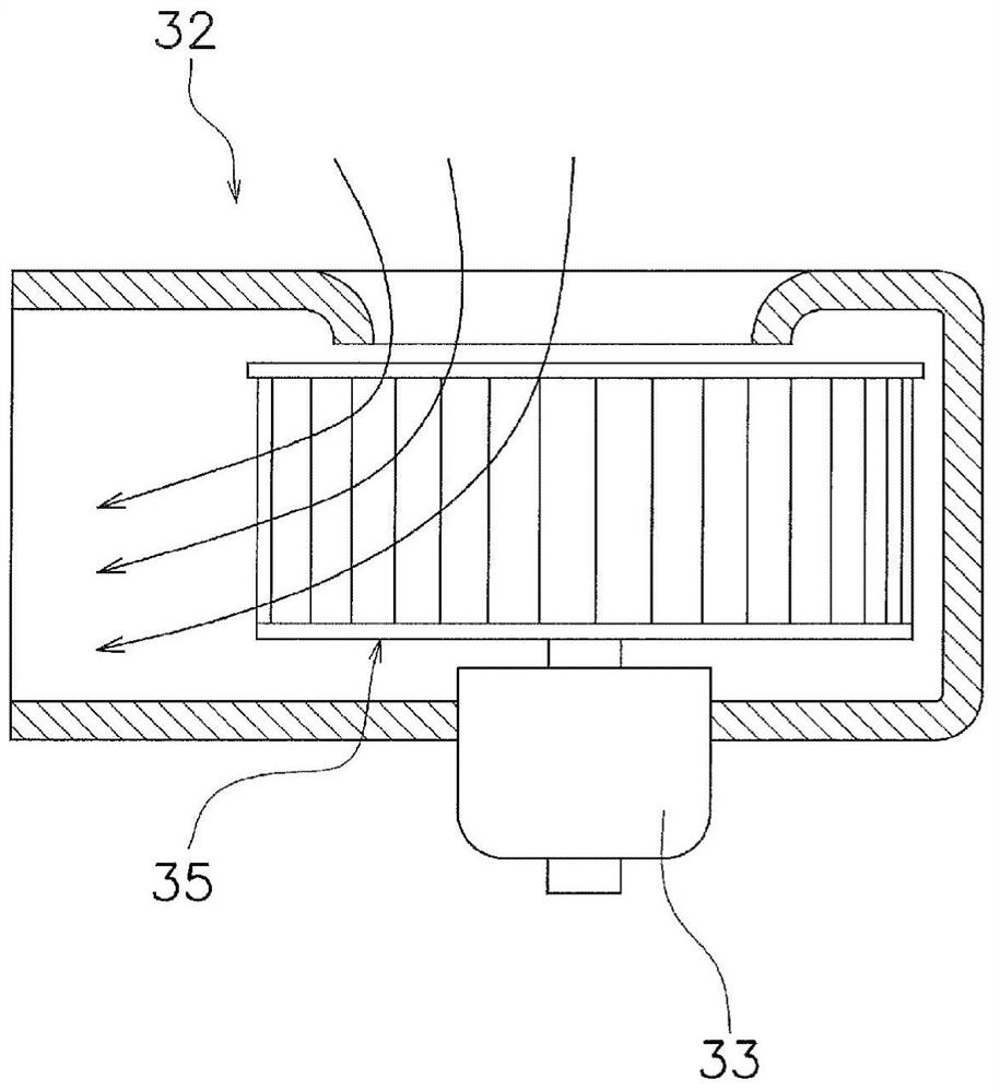
[0244] In the above-mentioned second embodiment, the case where the fan motor 33 functions as an actuator for changing the amount of supplied air has been described. However, the actuator for changing the amount of supplied air in the second embodiment is not limited to the fan motor 33 . For example, as multiple executors, it is also possible to use Figure 5 The drive motor 39 for the damper 38 is shown. Figure 5 The blower motor 33 of the blower blower 32 shown may be a motor of the type whose rotation speed can be changed, as in the second embodiment, or a motor whose rotation speed cannot be changed. When the fan motor 33 is of a type whose rotational speed cannot be changed, for example, only the damper 38 changes the amount of air supplied from the fan unit 30 to the outlet unit 70 (air volume). On the other hand, when the fan motor 33 is of a type whose rotation speed can be changed, not only the opening degree of the damper 38 is changed, but also the amount of air...
PUM
 Abstract
Description
Claims
Application Information
 - R&D
- Intellectual Property
- Life Sciences
- Materials
- Tech Scout
- Unparalleled Data Quality
- Higher Quality Content
- 60% Fewer Hallucinations
Browse by: Latest US Patents, China's latest patents, Technical Efficacy Thesaurus, Application Domain, Technology Topic, Popular Technical Reports.
© 2025 PatSnap. All rights reserved.Legal|Privacy policy|Modern Slavery Act Transparency Statement|Sitemap|About US| Contact US: help@patsnap.com


