
Heat exchanger and refrigeration cycle apparatus

a technology of heat exchanger and cycle apparatus, which is applied in the direction of indirect heat exchangers, light and heating apparatus, refrigeration components, etc., can solve the problems of heat exchanger performance degradation, heat exchange efficiency degradation, etc., to improve heat exchange efficiency, and prevent the effect of heat exchange efficiency reduction

Active Publication Date: 2022-05-10
MITSUBISHI ELECTRIC CORP
View PDF11 Cites 0 Cited by
  • Summary
  • Abstract
  • Description
  • Claims
  • Application Information

AI Technical Summary

Benefits of technology

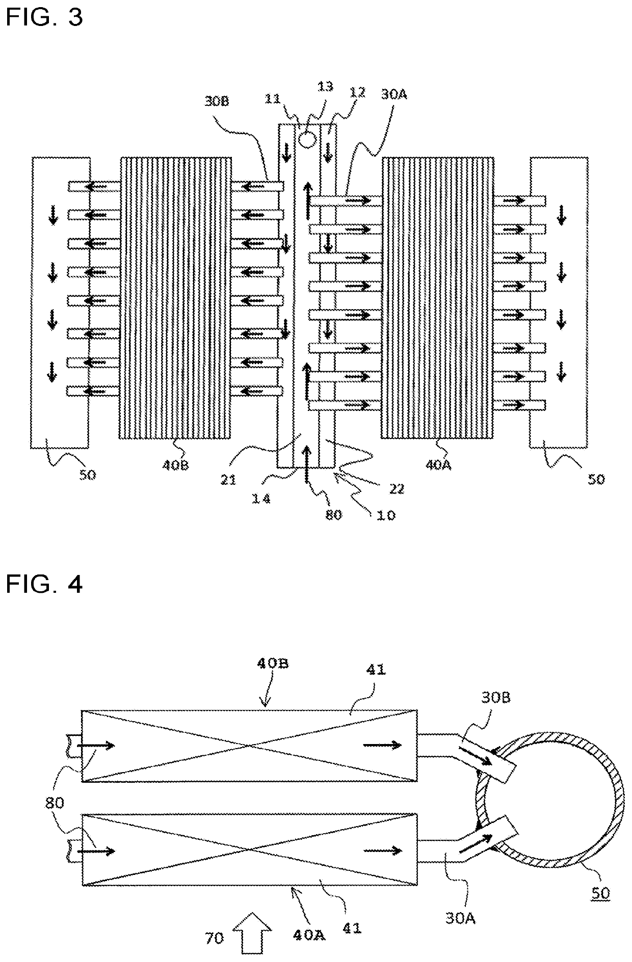
[0010]In a heat exchanger according to one embodiment of the present invention, a liquid refrigerant is allowed to flow at a higher rate to the heat transfer tubes of the heat exchanger core disposed on the windward side of the air flow. By allowing a liquid refrigerant to flow at a higher rate to the heat exchanger core disposed on the windward side in which the temperature difference between the liquid refrigerant and air is relatively large, the heat exchanger can improve its heat exchange efficiency.
[0011]In a refrigeration cycle apparatus according to one embodiment of the present invention, a second refrigerant circuit that bypasses the heat exchanger including the multiple heat exchanger cores includes a flow control valve that is connected to an upper portion of a gas-liquid separator and that adjusts the flow rate of the refrigerant. Thus, by opening or closing the flow control valve in accordance with an operation load of the refrigeration cycle apparatus, the heat exchanger can improve the heat exchange efficiency or prevent reduction of the heat exchange efficiency.

Problems solved by technology

Thus, the performance in distributing the liquid refrigerant to the heat transfer tubes to the heat exchanger core may be degraded, and the heat exchanger may degrade its performance.

Method used


Image

  • Heat exchanger and refrigeration cycle apparatus
  • Heat exchanger and refrigeration cycle apparatus
  • Heat exchanger and refrigeration cycle apparatus

Examples


embodiment 1

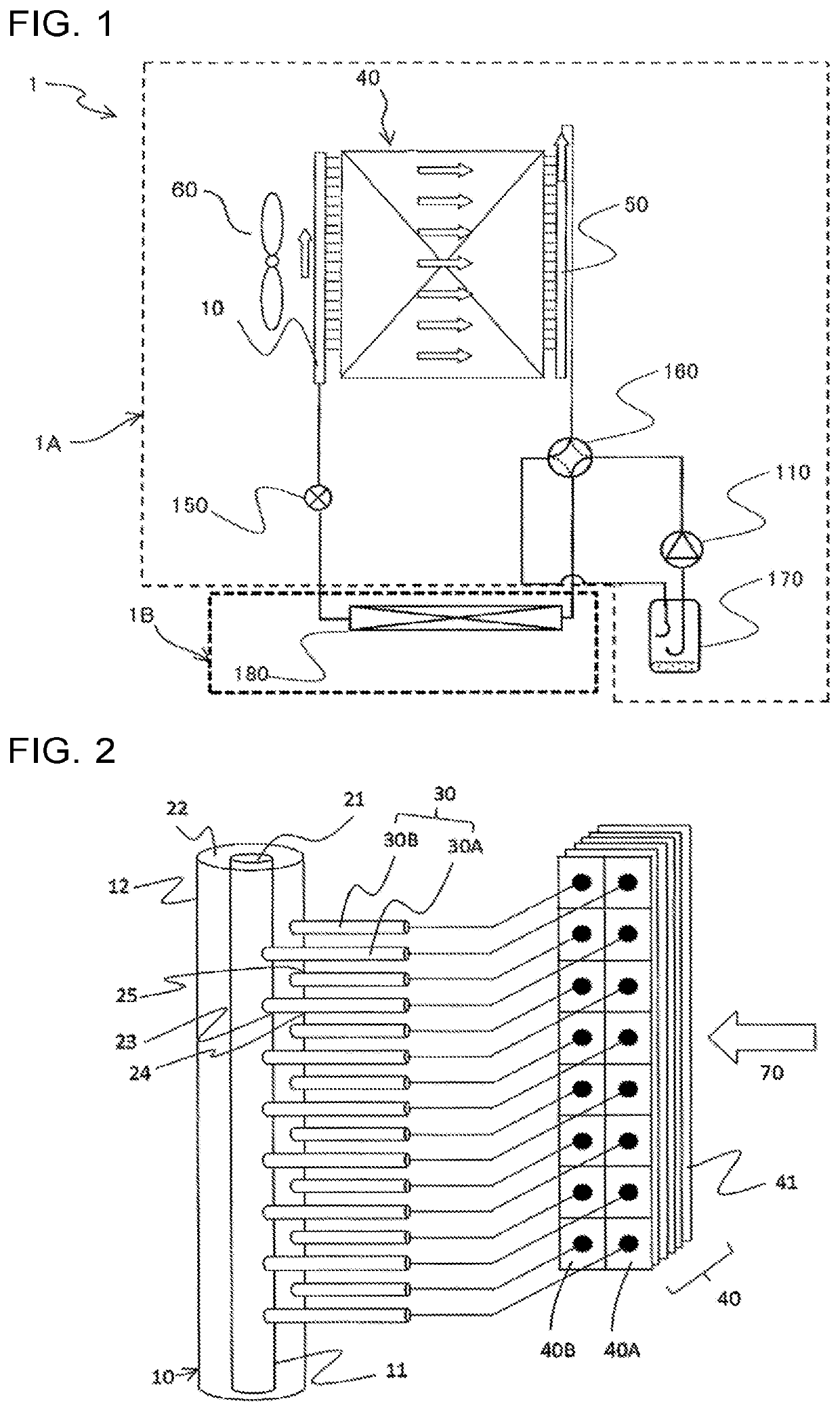
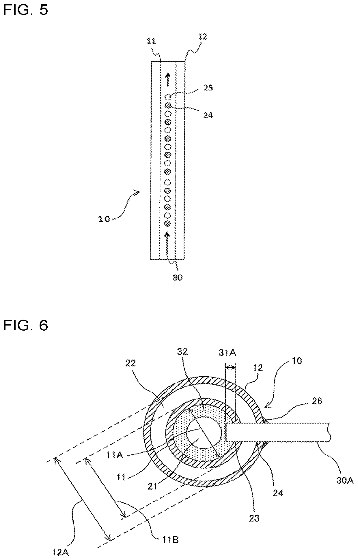
[0054]FIG. 1 is a schematic diagram of a refrigerant cycle configuration of a refrigeration cycle apparatus according to Embodiment 1 of the present invention. FIG. 2 is a schematic diagram of a structure of a header refrigerant distributor according to Embodiment 1. A refrigeration cycle apparatus 1 according to Embodiment 1 is an air-conditioning apparatus that performs air-conditioning of a room, which is subjected to air conditioning, and includes a heat source side unit 1A and a use side unit 1B. The heat source side unit 1A forms, together with the use side unit 1B, a refrigeration cycle that circulates refrigerant to remove or supply heat for air conditioning. The heat source side unit 1A is disposed outdoor. The heat source side unit 1A includes a compressor 110, a flow path switching device 160, a heat source side heat exchanger 40, a throttle device 150, an accumulator 170, and a fan 60. The use side unit 1B is disposed in a room that is subjected to air conditioning, and ...

embodiment 2

[0072]With reference to FIG. 10 to FIG. 13, Embodiment 2 of the present invention will be described. In FIG. 10 to FIG. 13, components the same as or equivalent to those in Embodiment 1 are denoted with the same reference signs, and components the same as those in Embodiment 1 will not be fully described. FIG. 10 is a schematic diagram of a structure of a header refrigerant distributor according to Embodiment 2 of the present invention. Embodiment 2 differs from Embodiment 1 in that the heat source side heat exchanger 40 is formed from heat exchanger cores in three rows. In Embodiment 2, the heat source side heat exchanger 40 includes a heat exchanger core 40A in a first row, a heat exchanger core 40B in a second row, and a heat exchanger core 40C in a third row, arranged from the windward side. The heat transfer tubes 30A are connected to the inner pipe 11, and the heat transfer tubes 30B are connected to the outer pipe 12. The heat transfer tubes 30A are connected to the heat exch...

embodiment 3

[0077]Embodiment 3 of the present invention will now be described with reference to FIG. 14 to FIG. 18. In FIG. 14 to FIG. 18, components the same as or equivalent to those in Embodiment 1 and Embodiment 2 are denoted with the same reference signs, and components the same as those in Embodiment 1 and Embodiment 2 will not fully be described. FIG. 14 is a schematic diagram of a structure of a heat source side heat exchanger according to Embodiment 3 of the present invention. The header refrigerant distributor 10 includes an inner pipe 11 and an outer pipe 12 and has a double pipe structure. The inner pipe flow path 21 is defined by the inner side of the inner pipe 11. The annular flow path 22 is defined by the outer side of the inner pipe 11 and the inner side of the outer pipe 12, and has an annular cross section. The inner pipe 11 has insertion holes 23 into which the heat transfer tubes 30A are inserted. The outer pipe 12 has insertion holes 24 into which the heat transfer tubes 3...


PUM


Abstract

A heat exchanger includes heat exchanger cores connected to a distributor. The inside of the distributor is divided into refrigerant flow paths, allowing the refrigerant to flow from one of the refrigerant flow paths to another one of the refrigerant flow paths. The heat transfer tubes of one of the heat exchanger cores disposed on a windward side of a flow of the air fed to the heat exchanger are connected to at least one of the refrigerant flow paths disposed in the distributor on an upstream side of a flow of the refrigerant. The heat transfer tubes of one of the heat exchanger cores disposed on a leeward side of the flow of the air fed to the heat exchanger are connected to at least one of the refrigerant flow paths disposed in the distributor on a downstream side of the flow of the refrigerant.

Description

CROSS-REFERENCE TO RELATED APPLICATIONS[0001]This application is a United States national stage application of International Application No. PCT / JP2017 / 024193, filed Jun. 30, 2017, which designates the United States and the entire contents of each of the above applications are hereby incorporated herein by reference in entirety.TECHNICAL FIELD[0002]The present invention relates to a heat exchanger and a refrigeration cycle apparatus that include a header that distributes refrigerant.BACKGROUND ART[0003]A heat exchanger of an existing air-conditioning apparatus includes a heat exchanger core that includes multiple heat transfer tubes and multiple fins, and a header to which the heat transfer tubes are connected. Under the conditions where refrigerant circulates in a refrigerant cycle of an air-conditioning apparatus at a low flow rate, a liquid refrigerant may fail to flow to an upper portion of the header. In addition, with the effect of gravity, a liquid refrigerant flows to a lowe...

Claims


Application Information

Patent Timeline
Patent Type & Authority Patents(United States)
IPC IPC(8): F25B39/02F25B39/00F25B41/00F28F9/02F25B13/00F28D1/053F28D21/00
CPCF25B39/00F25B41/00F28F9/0202F25B13/00F28D1/05391F28D2021/0071F28D2021/0084F25B41/42F28D1/05333F28F1/32F28F9/027F28F9/0214
Inventor MINAMI, SHINICHIROONAKA, YOJI
Owner MITSUBISHI ELECTRIC CORP
Learn More