Supercharge Your Innovation With Domain-Expert AI Agents!

Silicone oil removing equipment

A technology of equipment and silicone oil, which is applied in the field of silicone oil removal equipment, can solve the problems of excess silicone oil collection, uneven silicone oil volume, etc., and achieve the effects of reducing manufacturing costs, increasing efficiency, and uniform oil volume

Pending Publication Date: 2021-11-30
广东杰联新材料有限公司
View PDF0 Cites 0 Cited by
  • Summary
  • Abstract
  • Description
  • Claims
  • Application Information

AI Technical Summary

Problems solved by technology

[0005] The invention provides a device for removing silicone oil, which solves the problem that the amount of silicone oil is different during coating and the excess silicone oil cannot be collected

Method used


Image

  • Silicone oil removing equipment
  • Silicone oil removing equipment
  • Silicone oil removing equipment

Examples


no. 1 example

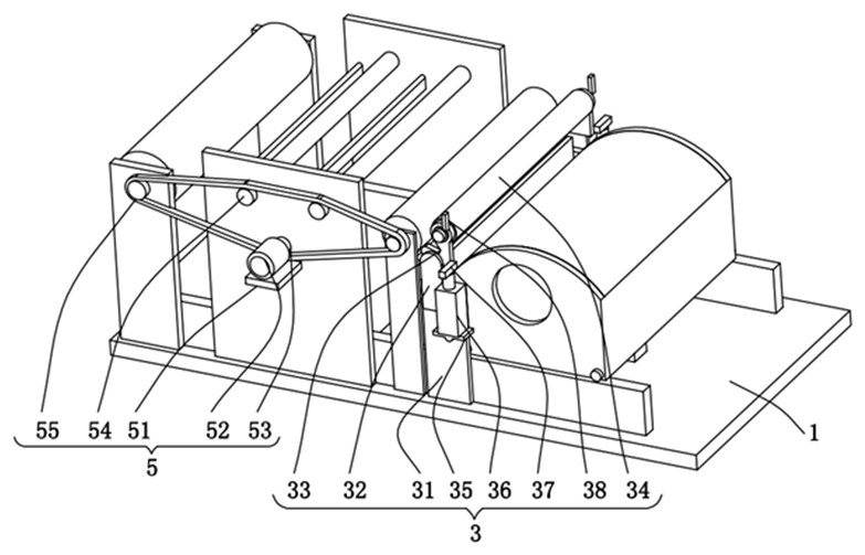
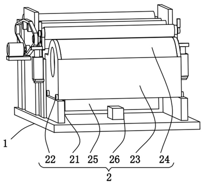
[0029] Please refer to figure 1 , figure 2 with image 3 ,in, figure 1 A schematic structural view of the first embodiment of the silicon oil removal equipment provided by the present invention; figure 2 for figure 1 The structural schematic diagram of the air knife assembly shown in the top view; image 3 for figure 1 The schematic diagram of the structure of the side of the bottom plate is shown. Silicone oil removal equipment, including: bottom plate 1;

[0030] The collection assembly 2, the bottom of the collection assembly 2 is arranged on the right side of the top of the bottom plate 1;

[0031] The air knife assembly 3, the bottom of the air knife assembly 3 is arranged on the top of the bottom plate 1;

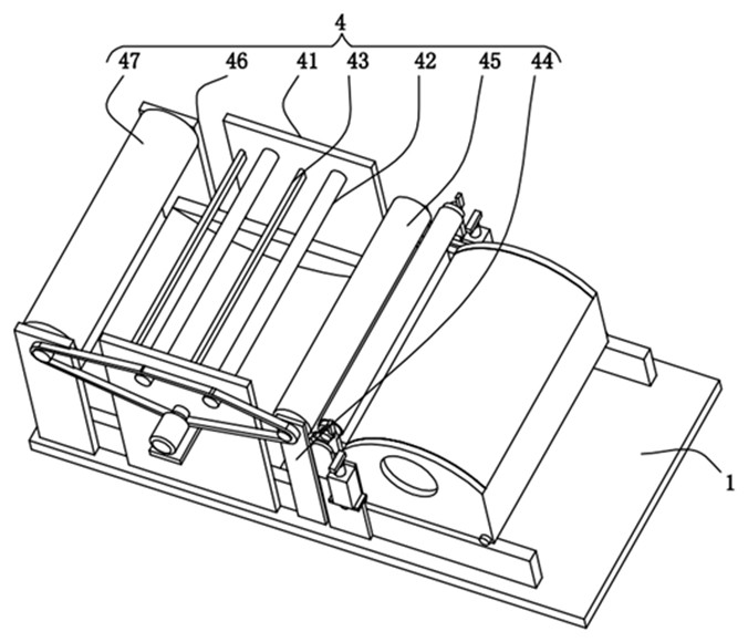
[0032] The scraper assembly 4, the bottom of the scraper assembly 4 is arranged on the top of the bottom plate 1;

[0033] The power assembly 5 , the back of the power assembly 5 is arranged on the front of the scraper assembly 4 .

[0034] The collection ...

no. 2 example

[0046] Please refer to Figure 4 ,in, Figure 4 It is a schematic structural diagram of the second embodiment of the silicon oil removal equipment provided by the present invention. Based on the silicon oil removal device provided in the first embodiment of the present application, the second embodiment of the present application proposes another silicon oil removal device. The second embodiment is only a preferred mode of the first embodiment, and the implementation of the second embodiment will not affect the independent implementation of the first embodiment.

[0047] Specifically, the difference between the silicone oil removal equipment provided in the second embodiment of the present application is that an adjustment assembly 6 is provided on the back of the air knife assembly 3 .

[0048] The adjustment assembly 6 includes two adjustment plates 61, the fronts of the two adjustment plates 61 pass through the air knife assembly 3 and extend the outside of the air knife ...


PUM


Abstract

The invention provides silicone oil removing equipment. The silicone oil removing equipment comprises a bottom plate, a collecting component, an air knife component, a scraping plate component and a power component, wherein the bottom of the collecting component is arranged on the right side of the top of the bottom plate; the bottom of the air knife component is arranged at the top of the bottom plate; the bottom of the scraping plate component is arranged at the top of the bottom plate; the back face of the power component is arranged on the front face of the scraping plate component, the collecting component comprises two track plates, the bottoms of the two track plates are fixedly connected with the top of a bottom plate, track wheels are arranged on the tops of the two track plates, a collecting box is arranged between the opposite sides of the two track wheels, and a box cover is arranged at the top of the collecting box. According to the silicone oil removing equipment, through cooperation of the collecting component and the air knife component, redundant oil on the surfaces of raw materials can be removed and then collected, so that the raw materials are saved, and meanwhile, the using efficiency of the equipment is improved.

Description

technical field [0001] The invention relates to the field of silicone oil removal equipment, in particular to a silicone oil removal equipment. Background technique [0002] The coating machine is mainly used for the surface coating process production of film, paper, etc. This machine is to coat the rolled substrate with a layer of glue, paint or ink with specific functions, and then wind it up after drying. It uses a special The multi-functional coating head can realize various forms of surface coating production. The winding and unwinding of the coating machine is equipped with a full-speed automatic film splicing mechanism, and the PLC program tension closed-loop automatic control. [0003] When the existing coating machine is spraying silicone oil, because the amount of oil sprayed by the spraying device cannot be controlled, the spraying amount and uniformity are not uniform, and the existing coating machine cannot recover the excess silicone oil. This will lead to a l...

Claims


Application Information

Patent Timeline
IPC IPC(8): B05C11/10B05C11/02B05C1/12
CPCB05C11/1039B05C11/028B05C1/12
Inventor 麦锦活
Owner 广东杰联新材料有限公司
Features
  • R&D
  • Intellectual Property
  • Life Sciences
  • Materials
  • Tech Scout
  • Unparalleled Data Quality
  • Higher Quality Content
  • 60% Fewer Hallucinations
Learn More