Bone implant internal crack flaw detection equipment
A technology for bone implants and internal cracks, which is used in measuring devices, analyzing solids using sonic/ultrasonic/infrasonic waves, and using sonic/ultrasonic/infrasonic waves for material analysis, etc. , to change the degree of bending, avoid waste, and achieve the effect of precise control
- Summary
- Abstract
- Description
- Claims
- Application Information
AI Technical Summary
Problems solved by technology
Method used
Image
Examples
Embodiment 1
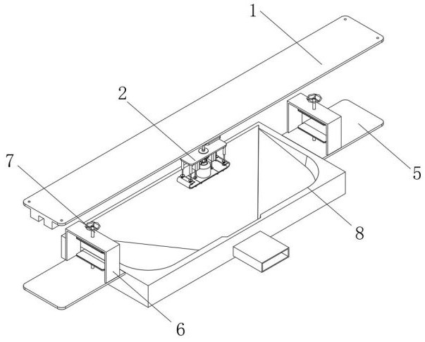
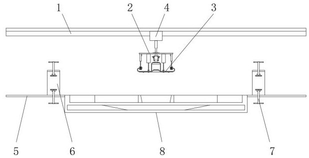
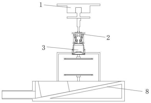
[0035] Such as figure 1 , 2 , 3, 4, 7, 8, a bone implant internal crack detection equipment, including slide rail 1, slider 4, support bar 5, U-shaped frame 6, fasteners 7 and ultrasonic flaw detector 9 , the lower end of the slide rail 1 is provided with a slider 4, the bottom of the slide rail 1 is provided with a support bar 5, the upper end of the support bar 5 is provided with a U-shaped frame 6 on both sides, and the frame of the U-shaped frame 6 is provided with a fastener 7 , the fastener 7 clamps the bone implant, the lower end of the slider 4 is provided with an angle adjustment mechanism 2, the lower end of the angle adjustment mechanism 2 is provided with a close fitting device 3, and the middle of the lower end of the angle adjustment mechanism 2 is provided with an ultrasonic flaw detector 9;
[0036] The sticking device 3 includes a straight plate 301, an elastic plate 303, an arc plate 304, a rag 306, an arc bar 307 and a through hole 308. The lower end of th...
Embodiment 2
[0039] Such as Figure 4 , 5As shown, the components that are the same as or corresponding to those in the first embodiment are marked with the corresponding reference numerals in the first embodiment. For the sake of simplicity, only the differences from the first embodiment will be described below. The difference is that the sticking device 3 also includes a spray head 302 and a limit waist hole 305. The two ends of the straight plate 301 are provided with a spray head 302, and the lower end of the arc plate 304 is provided with a limit waist hole 305. The spray head 302 is located at The gap between the arc bar 307 and the straight plate 301;
[0040] The two ends of the rag 306 are fixedly connected to the elastic plate 303, the rag 306 and the arc bar 307 are integrated, one end of the arc bar 307 is fixedly connected to the straight plate 301, and the rag 306 and the arc bar 307 contact the bone held by the fastener 7. There is ultrasonic coupling agent on the surface ...
Embodiment 3
[0042] Such as figure 1 , 2 , 3, 4, 5, 6, and 8, wherein the components that are the same as or corresponding to those in Embodiment 1 use the corresponding reference numerals as in Embodiment 1. For the sake of simplicity, only the differences from Embodiment 1 are described below. The difference is that the angle adjustment mechanism 2 includes a strip plate 201, a connecting head 202, a first linear driver 203, a universal ball 204, a limit ring 205, a storage box 206, a hose 207, and a second linear driver. 208, the third linear driver 209, the first ring 210, the first spring 211, the second ring 212 and the second spring 213, the lower end of the slider 4 is provided with the first linear driver 203, the first linear driver 203 The lower end of the connecting head 202 is provided with a connecting head 202, the lower end of the connecting head 202 is provided with a strip plate 201, the lower end of the strip plate 201 is provided with a universal ball 204, and the univ...
PUM
 Abstract
Description
Claims
Application Information
 - R&D
- Intellectual Property
- Life Sciences
- Materials
- Tech Scout
- Unparalleled Data Quality
- Higher Quality Content
- 60% Fewer Hallucinations
Browse by: Latest US Patents, China's latest patents, Technical Efficacy Thesaurus, Application Domain, Technology Topic, Popular Technical Reports.
© 2025 PatSnap. All rights reserved.Legal|Privacy policy|Modern Slavery Act Transparency Statement|Sitemap|About US| Contact US: help@patsnap.com


