Induction type traffic signal indicating device

A traffic signal and indicating device technology, which is applied in the field of inductive traffic signal indicating devices, to reduce congestion at intersections and avoid unusable effects

Active Publication Date: 2021-11-30
ZHENGZHOU UNIVERSITY OF AERONAUTICS
View PDF18 Cites 1 Cited by
  • Summary
  • Abstract
  • Description
  • Claims
  • Application Information

AI Technical Summary

Problems solved by technology

[0006] In view of the above situation, in order to overcome the defects of the prior art, the present invention provides an inductive traffic signal indicating device, which can And to the corresponding linkage, that is, when the municipal indicator light stops working, the device can be replaced in time and put into traffic command work, so that the traffic command at the intersection runs uninterrupted, ensuring the orderly and smooth progress of the traffic at the intersection, Moreover, the device can buffer the impact of the vehicle to a certain extent, and can better avoid the situation that it cannot be used due to damage caused by the impact of the vehicle.

Method used


Image

  • Induction type traffic signal indicating device
  • Induction type traffic signal indicating device
  • Induction type traffic signal indicating device

Examples


Embodiment 1

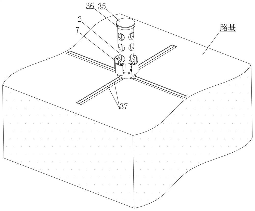
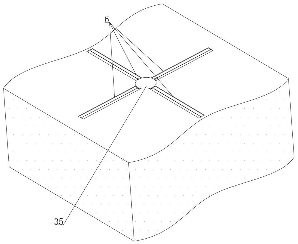
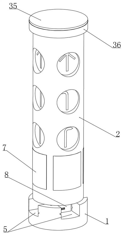
[0030] Embodiment 1, inductive traffic signal indicating device, as attached image 3 shown, including base 1, as attached Figure 10 As shown in the subgrade, there is a foundation pit 3 that is vertically slidably installed and matched with the base 1. The improvement of this scheme is that the base 1 is movably installed with a main indicator tube 2, as shown in the attached Figure 5 As shown, the main indicating tube 2 is vertically slidably installed with the auxiliary indicating tube 4 (the main indicating tube 2 and the auxiliary indicating tube 4 are provided with signal lights for going straight, turning right, and turning left and realizing the control of vehicle traffic at the intersection) , the main indicator tube 2 and the secondary indicator tube 4 are electrically connected with the municipal traffic control system, that is, when the municipal signal lights stop working, the municipal traffic control system controls the main indicator tube 2 and the secondary ...

Embodiment 2

[0037] Embodiment 2, on the basis of embodiment 1, as attached Figure 12 As shown, the bottom of the main indicator tube 2 is integrally provided with a slider 8 (the slider 8 is set as a cube and has the same width as the cross-shaped chute 5, and the width of the cross-shaped chute 5 and the cross-shaped chute 6 is the same). Figure 5 As shown, initially the slider 8 is located at the center of the cross-shaped chute 5, as shown in the attached Figure 8 , 9 As shown, a positioning spring 38 is connected between the positioning post 9 and the base 1, and the lower end surface of the main indicator tube 2 is provided with a positioning hole 10 that matches the positioning post 9, as shown in the attached Figure 11 As shown, there are two positioning columns 9 arranged diagonally in this solution. The positioning columns 9 are inserted into the positioning hole 10 under the action of the positioning spring 38 to realize the positioning effect between the main indicator tub...

Embodiment 3

[0038] Embodiment 3, on the basis of embodiment 2, as attached Figure 8 As shown, a circular ring 11 is vertically slidably installed on the bottom of the main indicator tube 2 coaxially, and a limit spring 12 is connected between the circular ring 11 and the limit spring 12. And the withdrawal rod 13 is inserted into the positioning hole 10, the upper end surface of the ring 11 is integrally provided with a limit rod 14 and the lower end surface of the protective plate 7 is provided with a limit hole 15 cooperating with the protective plate 7, as attached Figure 7 As shown, the limit rod 14 is chamfered on the side facing the protective plate 7, and when the limit rod 14 is inserted into the limit hole 15, the limit to the protective plate 7 is realized (overcoming the gap between the protective plate 7 and the main indicating cylinder 2). elastic force);

[0039] How the micro-controller controls the action of the limit device and removes the limit to the protective plate...


PUM


Abstract

The invention relates to an induction type traffic signal indicating device. The problems that an existing temporary signal lamp cannot replace a municipal signal lamp in time to direct traffic and is prone to being damaged due to collision are effectively solved. According to the technical scheme, the device can perform corresponding linkage according to the working condition of the municipal signal indicating lamp, namely, when the municipal signal indicating lamp stops working, the device can complete replacement in time and put into traffic guidance work, so that the traffic guidance at the intersection is uninterruptedly operated, the orderly and smooth proceeding of the traffic at the intersection is ensured, and the device can be used for buffering the collision of the vehicle to a certain degree, so that the situation that the vehicle cannot be used due to damage caused by the collision of the vehicle can be well avoided.

Description

technical field [0001] The invention belongs to the technical field of traffic control, and in particular relates to an inductive traffic signal indicating device. Background technique [0002] With the development of road traffic, more and more signal lights are spread all over the streets and intersections of the city to control the orderly and safe passage of vehicles, especially at some intersections with large vehicle traffic, the role of signal lights is even more important. , because the indicator light is connected to the municipal power supply, when the municipal power supply fails (natural disasters such as heavy rain, strong wind) or the power is cut off due to line maintenance, the indicator light at the intersection will stop working and the traffic at the intersection will be paralyzed; [0003] When the above situation occurs, there are usually municipal personnel who will place temporary signal lights in the middle of the intersection to act as temporary traf...

Claims


Application Information

Patent Timeline
IPC IPC(8): G08G1/0955F16F15/067
CPCG08G1/0955F16F15/067
Inventor 张磊贾利宾刘硕张帆赵晓雨马续桐
Owner ZHENGZHOU UNIVERSITY OF AERONAUTICS
Why Eureka
Try Eureka