Balance ability testing system and application thereof
A technology for testing system and balance ability, applied in the field of ergonomics, can solve problems such as not supporting pitching motion around bare joints, unable to test human balance ability parameters, etc., to achieve the effect of improving balance ability
- Summary
- Abstract
- Description
- Claims
- Application Information
AI Technical Summary
Problems solved by technology
Method used
Image
Examples
Embodiment 1
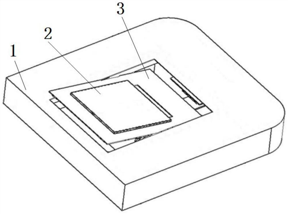
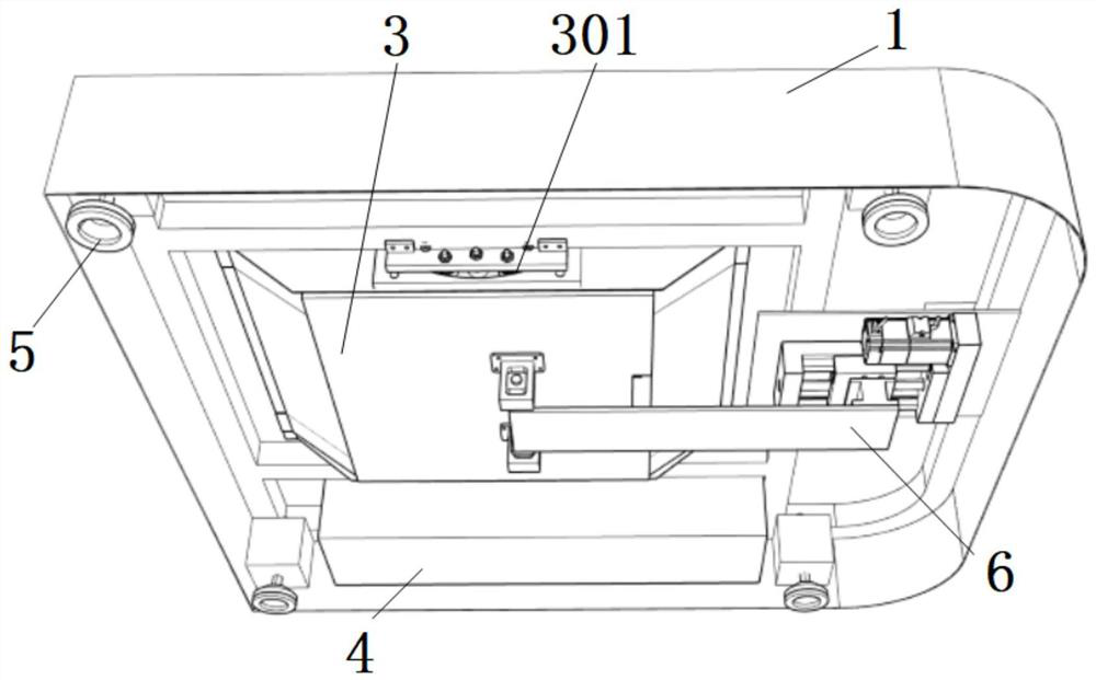
[0046] Specifically, pulleys are respectively fixedly installed on the left and right side walls of the installation hole of the base 1, and U-shaped rails 301 are opened on the left and right side walls of the pitch motion box 3 respectively. The pulleys on the left and right side walls are respectively located in the U-shaped track 301 on the left and right side walls of the pitch motion box 3 . A pitching motion driving mechanism is arranged in the base 1, the pitching motion driving mechanism is arranged on the rear side of the pitching motion box 3, the front end of the pitching motion driving mechanism is hinged with the bottom of the pitching motion box 3, and can drive The pitching motion box 3 slides along the U-shaped track 301 relative to the pulleys fixed on the base 1, thereby realizing the pitching motion.
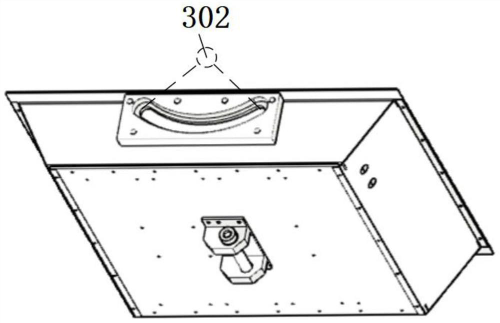
[0047] preferred, such as image 3As shown, the shapes of the two U-shaped rails 301 on the pitching motion box 3 are arc-shaped, the two arc-shaped tracks ...
Embodiment 2
[0049] The pitching motion drive mechanism includes a first linear module 6 and a first motor, and the moving end of the first linear module 6 is hingedly connected to the bottom of the pitching box 3, specifically, at the bottom of the pitching box 3 The lower surface of the bottom plate is provided with two lifting lugs, and holes are respectively opened on the two lifting lugs. The front end is provided with a hole, and the movable shaft passes through the hole, so that the hinge of the first linear module 6 and the pitching box 3 is realized by the movable shaft. When the first linear module 6 moves back and forth, the pitching box 3 The U-shaped rails 301 on both sides can move along the pulleys fixedly installed on the base 1 . Since the U-shaped rails 301 are arc-shaped, the pitching box 3 will move along the U-shaped rails 301 .
[0050] The present invention ensures that the direction of motion of the pitching box 3 will not be locked through the hinged connection, an...
Embodiment 3
[0052] Such as Figure 4 As shown, the pitching motion box 3 includes: a housing 303 , a base bracket 304 , a forward and backward motion driving mechanism and a sensor unit. The sensor unit includes a horizontal sensor unit 8 and a vertical sensor unit 7 .
[0053] The forward and backward movement driving mechanism is arranged in the inner cavity of the housing 303, and the forward and backward movement driving mechanism is located under the foot pedal 2, and can drive the foot pedal 2 to move forward and backward. Such as Figure 4 As shown, the forward and backward motion drive mechanism includes a second linear module 9 and a second motor.
[0054] Preferably, the housing 303 is enclosed by an upper end face, a lower end face, a left side wall, a right side wall, a front side wall, and a rear side wall, wherein the upper end face and the lower end face are arranged in parallel, and both are rectangular in shape, and The area of the end surface is larger than the area...
PUM
 Abstract
Description
Claims
Application Information
 - R&D
- Intellectual Property
- Life Sciences
- Materials
- Tech Scout
- Unparalleled Data Quality
- Higher Quality Content
- 60% Fewer Hallucinations
Browse by: Latest US Patents, China's latest patents, Technical Efficacy Thesaurus, Application Domain, Technology Topic, Popular Technical Reports.
© 2025 PatSnap. All rights reserved.Legal|Privacy policy|Modern Slavery Act Transparency Statement|Sitemap|About US| Contact US: help@patsnap.com


