Refrigeration equipment for refrigeration house

A technology for refrigeration equipment and cold storage, which is used in refrigerators, refrigeration components, refrigeration and liquefaction, etc., can solve the problems of hindering the heat transfer of air refrigerants, reducing cooling efficiency, and poor cooling effect, so as to facilitate heat transfer, avoid blocking, increase The effect of work efficiency

Pending Publication Date: 2021-12-03
江苏飒雪制冷设备工程有限公司
View PDF0 Cites 0 Cited by
  • Summary
  • Abstract
  • Description
  • Claims
  • Application Information

AI Technical Summary

Problems solved by technology

The compressor sucks the lower-pressure working medium vapor from the evaporator, raises its pressure, and then sends it to the condenser, where it is condensed into a higher-pressure liquid, which becomes a higher-pressure liquid after being throttled by the throttle valve. After the low-temperature liquid is sent to the evaporator, it absorbs heat and evaporates in the evaporator to become steam with a lower pressure, and then sends it to the inlet of the compressor to realize the refrigeration cycle. The existing refrigeration equipment mainly has the following problems when working: the first 1. After the evaporator of the cold storage is used for a period of time, a layer of frost forms on the surface of the evaporator, and the frost adheres to the heat exchange tubes and cooling fins of the evaporator, hindering the gap between the air and the refrigerant flowing in the heat exchange tubes. The heat transfer, thus, the cooling efficiency is reduced in a relatively short time
Second, the condenser of the refrigeration equipment will generate a lot of heat during the working process. The traditional cooling method usually uses water spraying. This method requires continuous spraying of cold water to cool down. This process often wastes a lot of water. resources, and the cooling effect is poor

Method used


Image

  • Refrigeration equipment for refrigeration house
  • Refrigeration equipment for refrigeration house
  • Refrigeration equipment for refrigeration house

Examples


Embodiment Construction

[0020] In order to have a further understanding of the purpose, structure, features, and functions of the present invention, the following detailed descriptions are given in conjunction with the embodiments.

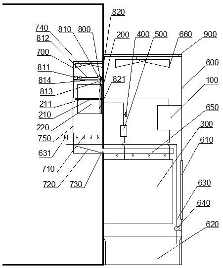
[0021] like figure 1 , a cold storage refrigeration equipment, including a compressor 100, an evaporator 200, a condenser 300, a throttle valve 400 and a drying filter 500, the suction port of the compressor 100 is connected to the evaporator 200, and the compressor The air outlet of 100 is connected to the inlet of the condenser 300 through pipelines, the outlet of the condenser 300 is connected to the drying filter 500 through pipelines, and the drying filter 500 is connected to the evaporator 200 through pipelines. A throttle valve 400 is arranged on the pipeline between the filter drier 500 and the evaporator 200 to realize the successful operation of the entire refrigeration cycle of the refrigeration equipment, and also includes a main body box 600 and an evaporati...


PUM


Abstract

The invention provides refrigeration equipment for a refrigeration house. The refrigeration equipment comprises a main body box and an evaporation box, wherein a compressor, a condenser, a throttle valve and a drying filter are arranged in the main body box; the evaporation box is fixed at the inner side of the refrigeration house; the main body box is arranged at the outer side of the refrigeration house; a water pan is further arranged below the condenser and connected with a first spray pipe through a first pipeline; the first spray pipe is arranged in the evaporation box; an inclined plate is arranged at the bottom of the evaporation box; a water flowing opening is formed in the lower side of the inclined plate; a second spray pipe is fixed to the water flowing opening, the second spray pipe extends into the main body box, and the second spray pipe is arranged above the condenser; and a defrosting mechanism is further arranged in the evaporation box and comprises a sliding device and a defrosting brush, the defrosting brush is fixed to the sliding device, and a brush head of the defrosting brush is attached to a heat exchange pipe and cooling fins. According to the refrigeration equipment, waste of water resources is reduced; heat transfer between air and a refrigerant flowing in the heat exchange pipe is facilitated, and the working efficiency of the equipment is improved; and the defrosting brush is comprehensive in defrosting, and energy consumption is reduced.

Description

technical field [0001] The invention relates to the technical field of cold storage equipment, in particular to a cold storage refrigeration equipment. Background technique [0002] Cold storage is a kind of equipment for storing cold air, which is mainly used for constant temperature storage of food, fruits and vegetables, meat, medicines, chemical raw materials, etc. The refrigerators in the prior art often use refrigeration equipment to reduce the temperature in the refrigerators to achieve the purpose of low-temperature storage. [0003] The refrigeration principle of the existing refrigeration equipment The function of the compressor is to compress the steam with a lower pressure into a steam with a higher pressure, so that the volume of the steam is reduced and the pressure is increased. The compressor sucks in the lower pressure working medium vapor from the evaporator, raises the pressure and then sends it to the condenser, where it condenses into a liquid with a hi...

Claims


Application Information

Patent Timeline
Patent Type & Authority Applications(China)
IPC IPC(8): F25D21/06F25D21/10F25D21/14F25B1/00F25B43/00F25B47/00
CPCF25D21/065F25D21/10F25D21/14F25B43/003F25B47/00F25B1/00
Inventor 孔祥扣
Owner 江苏飒雪制冷设备工程有限公司
Why Eureka
Try Eureka