Supercharge Your Innovation With Domain-Expert AI Agents!

Detector signal acquisition system

A signal acquisition system and detector technology, used in instruments, measuring devices, measuring ultrasonic/sonic/infrasonic waves, etc., can solve the problems of error-prone, labor-intensive, and time-consuming manual monitoring records

Pending Publication Date: 2021-12-03
11TH RES INST OF CHINA ELECTRONICS TECH GROUP CORP
View PDF8 Cites 0 Cited by
  • Summary
  • Abstract
  • Description
  • Claims
  • Application Information

AI Technical Summary

Problems solved by technology

The above is only a unit detector test process, such as a multi-element detector needs to repeat the above process many times to complete the test, because the manual test can only detect one channel at a time
Traditional testing methods are time-consuming and laborious, and manual monitoring records are prone to errors. Faced with the increasing production capacity

Method used


Image

  • Detector signal acquisition system
  • Detector signal acquisition system
  • Detector signal acquisition system

Examples


Embodiment Construction

[0032] Exemplary embodiments of the present disclosure will be described in more detail below with reference to the accompanying drawings. Although exemplary embodiments of the present disclosure are shown in the drawings, it should be understood that the present disclosure may be embodied in various forms and should not be limited by the embodiments set forth herein. Rather, these embodiments are provided for more thorough understanding of the present disclosure and to fully convey the scope of the present disclosure to those skilled in the art.

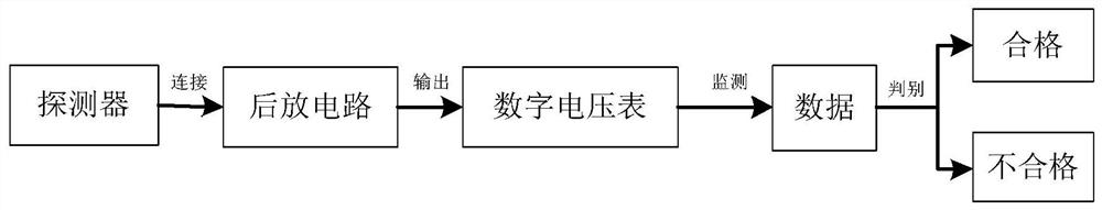
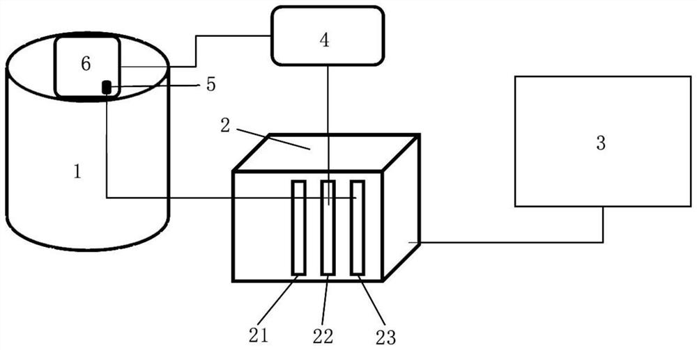
[0033] Embodiments of the present invention provide this kind of detector signal acquisition system, such as figure 2 shown, including:

[0034] The vibration table 1 is used to install the detector to be tested 6, and provides a vibration environment for the detector to be tested 6; the amplification circuit 4 is connected to the vibration table 1, and is used to obtain and amplify the detector to be tested 6 The noise signal of...


PUM


Abstract

The invention discloses a detector signal acquisition system, and the system comprises a vibration table which is used for installing a to-be-detected detector and providing a vibration environment for the to-be-detected detector; an amplifying circuit, connected with the vibration table and used for acquiring and amplifying a noise signal of the detector to be detected; an acceleration sensor, mounted on the table surface of the vibration table and used for acquiring a vibration signal of the to-be-detected detector in a vibration state; a control system, configured to receive the noise signal and the vibration signal and integrate the noise signal and the vibration signal to a software interface so as to realize dynamic monitoring of the detector to be detected; and a display, configured to present the dynamic monitoring process of the detector to be detected. Signals collected by the amplifying circuit and the acceleration sensor are received at the same time, so that manual noise monitoring and recording are not needed, and meanwhile automatic vibration noise collection of infrared detectors of different specifications can be supported.

Description

technical field [0001] The invention relates to the field of detector vibration and noise testing, in particular to a detector signal acquisition system. Background technique [0002] Infrared detectors will inevitably be affected by the mechanical vibration of the system in the operating environment, resulting in noise pulses, causing the noise voltage of the detector to rise suddenly under static (steady state), sometimes reaching dozens of times the static noise voltage. Interference is caused to the response signal pulse, which greatly reduces the tracking ability and detection distance of the detector. The vibration table is used to simulate the actual use environment, so the vibration and noise test is an important part of the test process. Only by accurately testing the vibration and noise can we judge whether the detector is qualified, so as to avoid unqualified infrared devices from reaching the user, which will affect the quality of the detector. Product image. ...

Claims


Application Information

Patent Timeline
Patent Type & Authority Applications(China)
IPC IPC(8): G01H9/00
CPCG01H9/00
Inventor 石佳节张研李进武石英赵楠许富翔封雪
Owner 11TH RES INST OF CHINA ELECTRONICS TECH GROUP CORP
Features
  • R&D
  • Intellectual Property
  • Life Sciences
  • Materials
  • Tech Scout
  • Unparalleled Data Quality
  • Higher Quality Content
  • 60% Fewer Hallucinations
Learn More