LED illumination control system

A technology of LED lighting and control system, which is applied in the direction of lighting devices, lighting and heating equipment, components of lighting devices, etc., can solve problems such as difficult to meet the user's adjustment of LED lighting brightness, and achieve the effect of ensuring stability

Active Publication Date: 2021-12-03
丰城市巨辉科技有限公司
View PDF9 Cites 0 Cited by
  • Summary
  • Abstract
  • Description
  • Claims
  • Application Information

AI Technical Summary

Problems solved by technology

[0003] LED lighting lamps can increase the brightness of LED lighting according to the increased current. In the prior art of LED lighting lamps, within the rated range of the power of LED lighting lamps, LED lighting lamps are generally provided with three levels of brightness for users to adjust. The number is too small, it is difficult to meet the needs of some users to adjust the brightness of LED lights

Method used


Image

  • LED illumination control system
  • LED illumination control system
  • LED illumination control system

Examples


Embodiment 1

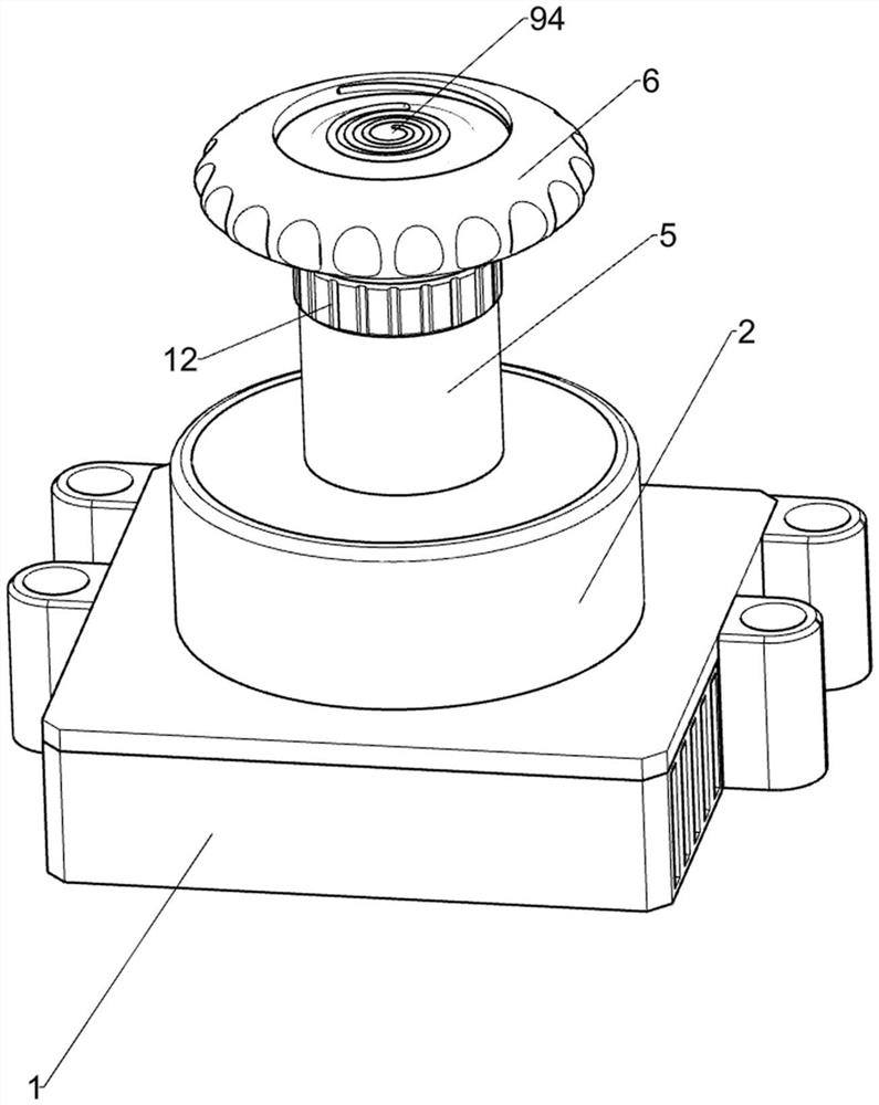
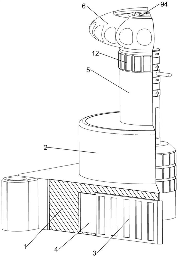
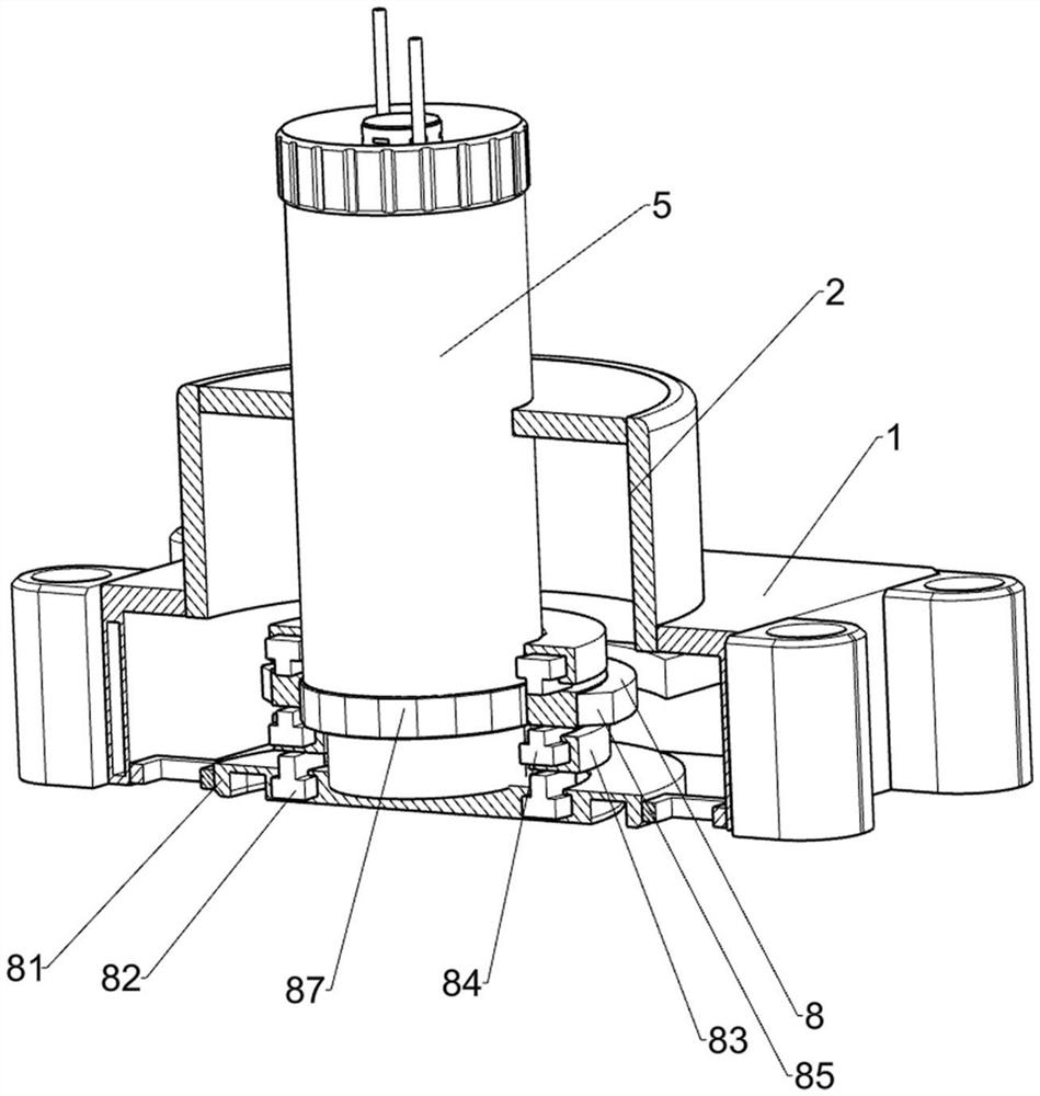
[0045] A LED lighting control system, such as Figure 1-Figure 12 , Figure 13 , Figure 14 , Figure 15 , Figure 16 and Figure 17 As shown, it includes a shell 1, a cylindrical cover 2, an n-shaped shell 3, a magnet plate 4, a cylinder body 5, a knob 6, a magnetic pole adjustment mechanism 7 and a light-on mechanism 8, and a cylindrical cover 2 is arranged on the top of the shell 1. The n-shaped shell 3 is slidingly connected, and the rear end of the n-shaped shell 3 is welded with two magnet plates 4. The magnet plates 4 and the shell 1 are mutually adsorbed. The user turns the adjustable knob 6, and the light-on mechanism 8 is positioned in the housing 1. The light-on mechanism 8 is used to turn on the LED lamp. The light-on mechanism 8 is provided with a magnetic pole adjustment mechanism 7.

[0046] The magnetic pole adjustment mechanism 7 includes a fixed cylinder 71, a fixed rod 72, a positive pole guide ring 73, a negative pole guide ring 74, a permanent magnet ...

Embodiment 2

[0050] On the basis of Example 1, such as Figure 13 and Figure 14 As shown, it also includes a sliding adjustment mechanism 10. The cylindrical cover 2 is provided with a sliding adjustment mechanism 10. The sliding adjustment mechanism 10 is used to adjust the resistance value of the device to adjust the brightness of the LED lamp or the light of different colors. The sliding adjustment mechanism 10 includes There are a fixed plate 101, a fixed lug 102, an arc-shaped resistance plate 103, a sliding lug 104, a sliding conductive plate 105 and a sliding conductive plate 106. The connecting piece 102 is also fixedly connected to the mounting plate 81 for outputting current to the LED lamp. The fixed connecting piece 102 is fixedly connected with an arc-shaped resistance plate 103 at one end, and the fixed plate 101 is provided with a first arc-shaped slide. Slot 107, the first arc-shaped chute 107 is slidably connected with a sliding lug 104 for introducing current, and the m...

Embodiment 3

[0055] On the basis of Example 2, such as Figure 10 , Figure 11 , Figure 12 and Figure 15 As shown, a synchronous opening mechanism 9 is also included. A synchronous opening mechanism 9 is provided in the multilateral sliding ring 87. The synchronous opening mechanism 9 is used to adjust the brightness of the LED lamp or open it while the lights of different colors are on. The synchronous opening mechanism 9 Including a connecting rod 91, a vertical rod 92, a third slider 93, a rotating cover 94 and a protrusion 95, the inner side of the multilateral sliding ring 87 is fixedly connected with two connecting rods 91, the connecting rods 91 run through the cylinder body 5, and the tops of the connecting rods 91 are fixed Connected with a vertical bar 92, the vertical bar 92 runs through the knob 6, the top of the vertical bar 92 is fixedly connected with a third slider 93, and the two third sliders 93 are jointly slidably connected with a rotating cover 94, and the rotating...


PUM


Abstract

The invention relates to the field of LED lighting, in particular to an LED lighting control system which comprises a shell, a cylindrical cover, an n-shaped shell, magnet plates, a barrel and the like. The cylindrical cover is arranged at the top of the shell, the n-shaped shell is slidably connected to the shell, two magnet plates are welded to the rear end of the n-shaped shell, the magnet plates and the shell attract each other, and the barrel is rotatably connected to the center of the cylindrical cover. A user manually pulls a knob upwards to change the position of a multilateral sliding ring, then rotates the knob according to requirements to change the position of a sliding conducting strip, and further controls the resistance value of an arc-shaped resistance plate to be increased or decreased, so that an LED lamp emits light with different brightness degrees, and the purpose of adjusting the illumination brightness of the LED lamp according to the requirements is achieved.

Description

technical field [0001] The invention relates to the field of LED lighting, in particular to an LED lighting control system. Background technique [0002] LED lighting can be applied to any occasion. LED lighting is light-emitting diode lighting. LED lighting uses solid semiconductor chips as light-emitting materials. In the semiconductor, the excess energy is released through the recombination of carriers to cause photon emission, which directly emits red, Yellow, blue, and green light, the lighting fixtures manufactured by using LED as a light source are LED lamps. LED lighting has the characteristics of small size, energy saving, long life, high brightness, and environmental protection. [0003] LED lighting lamps can increase the brightness of LED lighting according to the increased current. In the prior art of LED lighting lamps, within the rated range of the power of LED lighting lamps, LED lighting lamps are generally provided with three levels of brightness for users ...

Claims


Application Information

Patent Timeline
Patent Type & Authority Applications(China)
IPC IPC(8): H01H19/14F21V23/04H05B45/20
CPCH01H19/14F21V23/04H05B45/20F21Y2115/10Y02B20/30
Inventor 熊辉
Owner 丰城市巨辉科技有限公司
Why Eureka
Try Eureka