Anti-noise microphone with high electromagnetic compatibility
An electromagnetic compatibility and microphone technology, which is applied in the field of microphones, can solve the problem that the microphone has no anti-noise function, and achieve the effects of improving anti-noise effect, improving working stability, and preventing displacement
- Summary
- Abstract
- Description
- Claims
- Application Information
AI Technical Summary
Problems solved by technology
Method used
Image
Examples
Embodiment 1
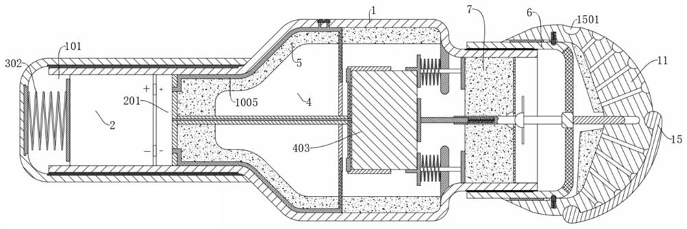
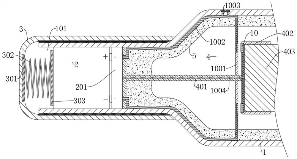
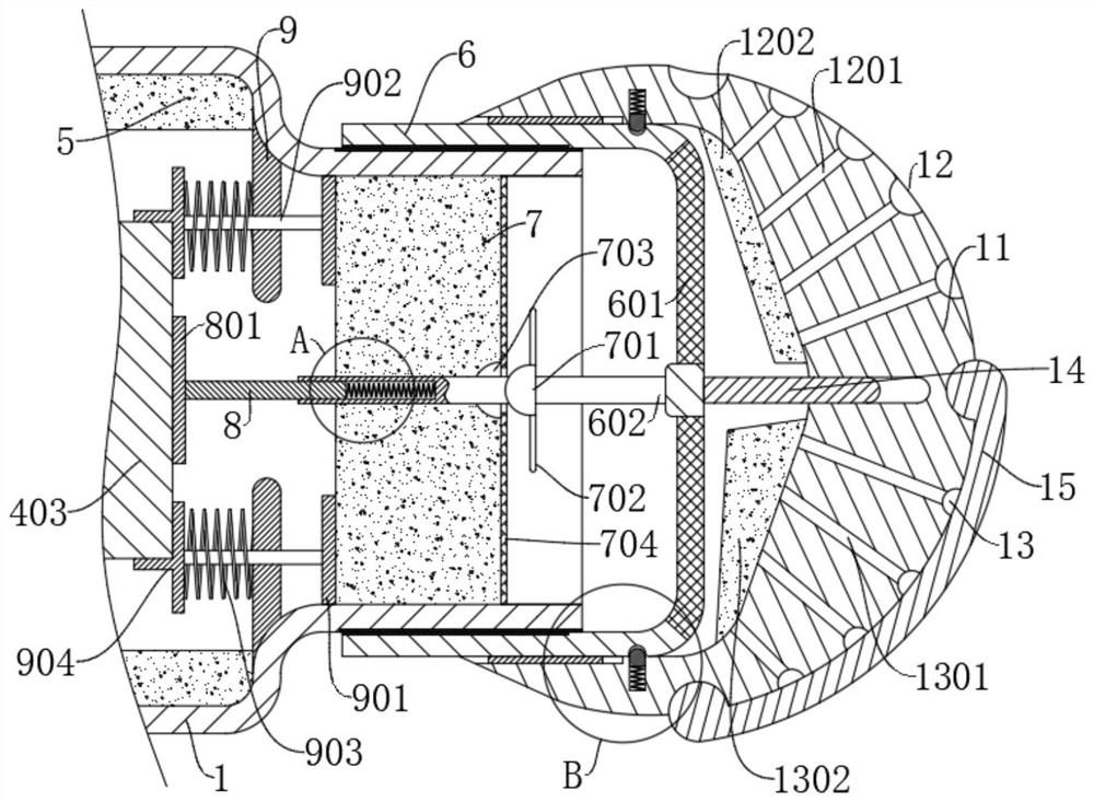
[0030] refer to Figure 1-6 , a high electromagnetic compatibility anti-noise microphone, including a housing 1 and a microphone assembly 403, and also includes: a hollow cavity 4, located in the housing 1; a connecting seat 402, connected in the hollow cavity 4, and the microphone assembly 403 is connected in Inside the connecting seat 402; the second sound-absorbing cotton 7 is slidably connected in the housing 1; the fixed network cable 704 is fixedly connected in the housing 1 and attached to the second sound-absorbing cotton 7; the threaded sleeve 6 is screwed in the housing At one end of 1, the threaded sleeve 6 is provided with a hollow net 601; the threaded sleeve 6 is provided with a fixing mechanism that can simultaneously compress and fix the network cable 704 and the microphone assembly 403; the outside of the threaded sleeve 6 is connected with an adjustment mechanism that can manually adjust the volume; The first sound-absorbing cotton 5 is wrapped inside the cas...
Embodiment 2
[0034] refer to Figure 1-6 , on the basis of Example 1, further,
[0035] The fixing mechanism includes a second connecting rod 602 and a second pressing plate 801, the second connecting rod 602 is rotatably connected to the inner wall of the threaded sleeve 6, the second connecting rod 602 is connected with a pressing rod 702, and the second connecting rod 602 is slidably connected with a third The connecting rod 8 , the second spring 802 is connected between the third connecting rod 8 and the inner wall of the second connecting rod 602 , and the second pressing plate 801 is connected to an end of the third connecting rod 8 away from the second connecting rod 602 .
[0036] The second connecting rod 602 is fixedly connected with a ball block 701, the pressure rod 702 is fixedly connected with the ball block 701, the second sound-absorbing cotton 7 is provided with a groove 703 corresponding to the ball block 701, and the second connecting rod 602 runs through the first Two ...
Embodiment 3
[0040] refer to Figure 1-6 , on the basis of Example 2, further,
[0041] The housing 1 is provided with a fixed plate 9, on which a sliding rod 902 is slidably connected, and the two ends of the sliding rod 902 are respectively connected with a push plate 901 and a centralizing plate 904, and the push plate 901 is attached to the second sound-absorbing cotton 7, The centralizing plate 904 is attached to the microphone assembly 403 , the third spring 903 is sleeved on the sliding rod 902 , and the third spring 903 is located between the centralizing plate 904 and the fixing plate 9 .
[0042] The pressing rod 702 drives the fixed wire 704 to move and squeeze the second sound-absorbing cotton 7 , and at the same time, the second sound-absorbing cotton 7 moves inwardly, pushing the push plate 901 to move, and the microphone assembly 403 is further fixed by the centralizing plate 904 .
[0043] At the same time, both ends of the third spring 903 are fixed on the centralizing pl...
PUM
 Abstract
Description
Claims
Application Information
 - R&D
- Intellectual Property
- Life Sciences
- Materials
- Tech Scout
- Unparalleled Data Quality
- Higher Quality Content
- 60% Fewer Hallucinations
Browse by: Latest US Patents, China's latest patents, Technical Efficacy Thesaurus, Application Domain, Technology Topic, Popular Technical Reports.
© 2025 PatSnap. All rights reserved.Legal|Privacy policy|Modern Slavery Act Transparency Statement|Sitemap|About US| Contact US: help@patsnap.com


