Vertical three-axis simulation rotary table with front yaw axis motor

A technology of yaw axis and motor rotor, which is applied in the direction of weapon accessories, direction control systems, offensive equipment, etc. It can solve the problems of shaft system design that is difficult to meet the requirements, motor torque transmission distance is long, unfavorable high-response indicators, etc. Achieve the effect of realizing the frequency response characteristics of the shafting, improving production efficiency and saving costs

Pending Publication Date: 2021-12-07
JIUJIANG PRECISION MEASURING TECH RES INST
View PDF0 Cites 0 Cited by
  • Summary
  • Abstract
  • Description
  • Claims
  • Application Information

AI Technical Summary

Problems solved by technology

[0005] The yaw shaft system of the three-axis vertical simulation turntable is the shaft system of the outermost ring, and the moment of inertia of this shaft system is also the largest. With the continuous improvement of the frequency response index in recent years, the previous shaft system design method is difficult to meet the requirements
[0008] In the past simulation turntable design, the motor is placed at the end of the main shaft, and the bearing assembly is closest to the U-shaped frame. This motor configuration will make the torque transmission distance of the motor too long, which is not conducive to achieving high-response indicators. The traditional motor The rotor will directly or indirectly cooperate with the bottom end surface of the main shaft; on the other hand, the connection between the U-shaped frame and the main shaft is fastened by screws and equipped with pins. This connection method requires difficult construction and complicated procedures

Method used


Image

  • Vertical three-axis simulation rotary table with front yaw axis motor
  • Vertical three-axis simulation rotary table with front yaw axis motor
  • Vertical three-axis simulation rotary table with front yaw axis motor

Examples


Embodiment Construction

[0027] The present invention will be described in further detail below in conjunction with the accompanying drawings.

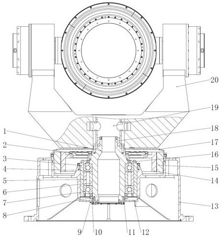
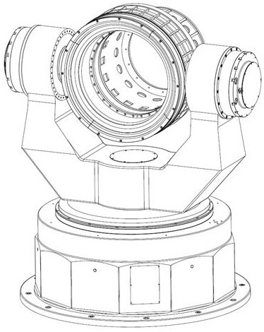
[0028] Such as Figure 1-Figure 7 As shown, a vertical three-axis simulation turntable with a yaw axis motor in front, including a base 13, the base 13 is provided with a main shaft 1, and a bearing assembly is installed on the main shaft 1 through a lock nut 8. The base 13 The upper end is fixed with an outer cover 17, and the upper side of the outer cover 17 is provided with a "U"-shaped frame 20, and the bottom of the "U"-shaped frame 20 is provided with a yaw hole 19, and the lower end of the "U"-shaped frame 20 is sleeved on the On the main shaft 1 , the yaw hole 19 is provided with an expansion sleeve 18 fitted on the main shaft 1 , and the base 13 is located on the upper side of the bearing assembly and provided with a motor fitted on the main shaft 1 .

[0029] The bearing assembly includes a bearing seat 3 fixedly connected to the base 13, a bearing...


PUM


Abstract

A vertical three-axis simulation rotary table with a front yaw axis motor comprises a base, a main shaft is arranged in the base, a bearing assembly is installed on the main shaft through a locking nut, an outer cover is fixed to the upper end of the base, a U-shaped frame is arranged on the upper side of the outer cover, a yaw hole is formed in the bottom of the U-shaped frame, and the lower end of the U-shaped frame is connected to the main shaft in a sleeving mode through the yaw hole. An expansion sleeve arranged on the main shaft in a sleeving mode is arranged in the yaw hole, and a motor arranged on the main shaft in a sleeving mode is arranged at the position, located on the upper side of the bearing assembly, in the base. The motor is placed at the upper part of the base, so that the axial distance from the torque of the motor to a load is shortened, and the torsional rigidity of the main shaft is improved; and the expansion sleeves are additionally arranged in the yaw holes of the main shaft and the U-shaped frame, so that the pin hole preparation process is omitted, the working efficiency is improved, the connection rigidity of the main shaft and the load can be increased, and the frequency response characteristic of the yaw axis of the three-axis simulation rotary table can be realized through the improvement in the two aspects.

Description

technical field [0001] The invention relates to a vertical three-axis simulation turntable with a yaw axis motor in front. Background technique [0002] As a platform for test verification, the three-axis electric turntable plays an important role in the development of missiles and aerospace vehicles. The missile guidance system is the core component of the missile and the aircraft. There are two main test methods for evaluating the performance of the guidance system: one is to obtain data during actual shooting or actual flight, and to find problems from it and continuously improve it; The simulation test equipment tests and evaluates various performance indicators of the guidance system on the ground. Since the dynamic characteristics of the missile (or aircraft) seeker are truly simulated under laboratory conditions, this kind of equipment has been more and more widely used, and it is suitable for high dynamic (or high response, high bandwidth) requirements are becoming...

Claims


Application Information

Patent Timeline
Patent Type & Authority Applications(China)
IPC IPC(8): F41G7/00
CPCF41G7/005
Inventor 刘喜平霍国亮徐玮珩
Owner JIUJIANG PRECISION MEASURING TECH RES INST
Why Eureka
Try Eureka