
Power distribution cabinet capable of expanding heat dissipation range and heat dissipation expanding method

A power distribution cabinet and range technology, which is applied in the field of expanding heat dissipation, can solve the problems of inability to effectively dissipate heat in different positions, affect heat dissipation efficiency, and small heat dissipation range, so as to achieve the effect of increasing heat dissipation range, expanding heat dissipation range, and improving service life

Pending Publication Date: 2021-12-07
宁波佳慧电气实业有限公司
View PDF0 Cites 3 Cited by
  • Summary
  • Abstract
  • Description
  • Claims
  • Application Information

AI Technical Summary

Problems solved by technology

[0003] In order to solve the problems raised in the above-mentioned background technology, the purpose of the present invention is to provide a power distribution cabinet that can expand the heat dissipation range and a method for expanding heat dissipation, which has the advantage of expanding the heat dissipation range, and solves the problem of the existing power distribution cabinets. During use, only a single fixed cooling fan is used for heat dissipation, and the heat dissipation range is small, which affects the heat dissipation efficiency and cannot effectively dissipate heat in different positions

Method used


Image

  • Power distribution cabinet capable of expanding heat dissipation range and heat dissipation expanding method
  • Power distribution cabinet capable of expanding heat dissipation range and heat dissipation expanding method
  • Power distribution cabinet capable of expanding heat dissipation range and heat dissipation expanding method

Examples


Embodiment Construction

[0030] The following will clearly and completely describe the technical solutions in the embodiments of the present invention with reference to the accompanying drawings in the embodiments of the present invention. Obviously, the described embodiments are only some, not all, embodiments of the present invention. Based on the embodiments of the present invention, all other embodiments obtained by persons of ordinary skill in the art without making creative efforts belong to the protection scope of the present invention.

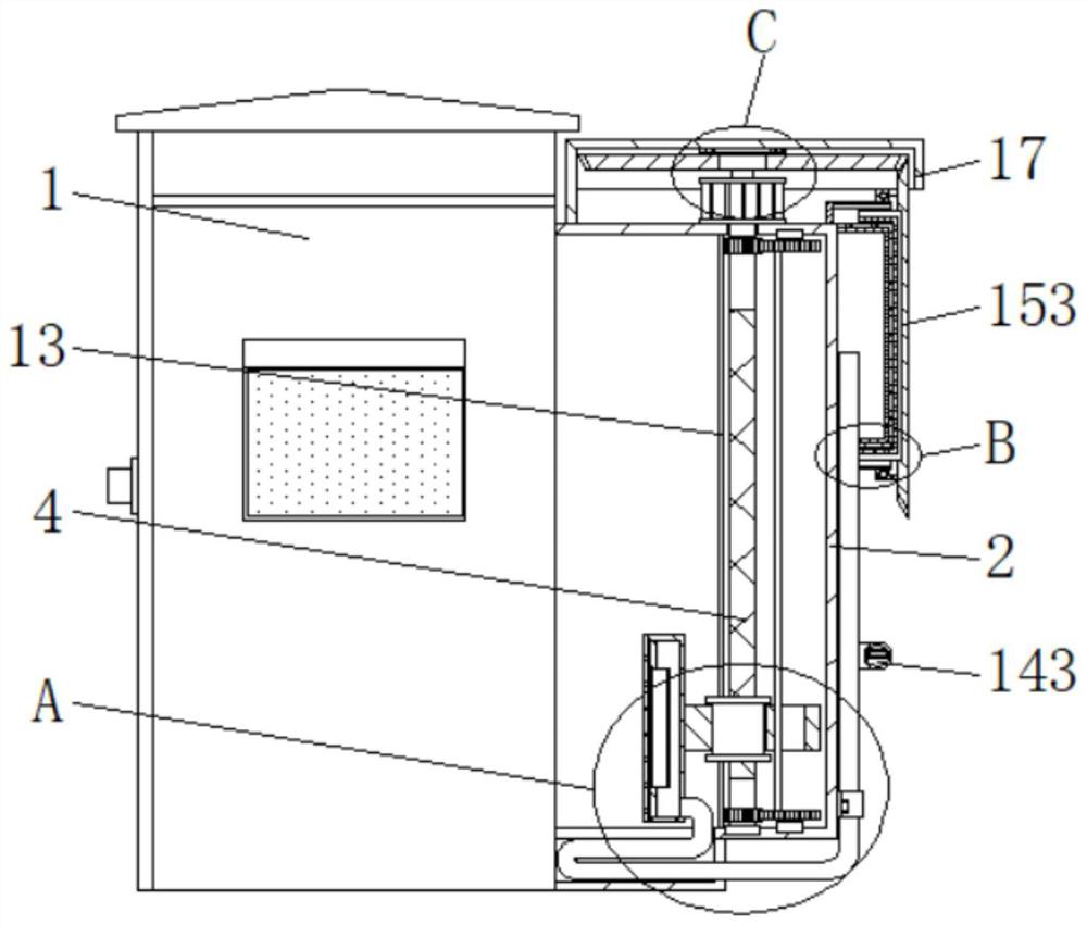
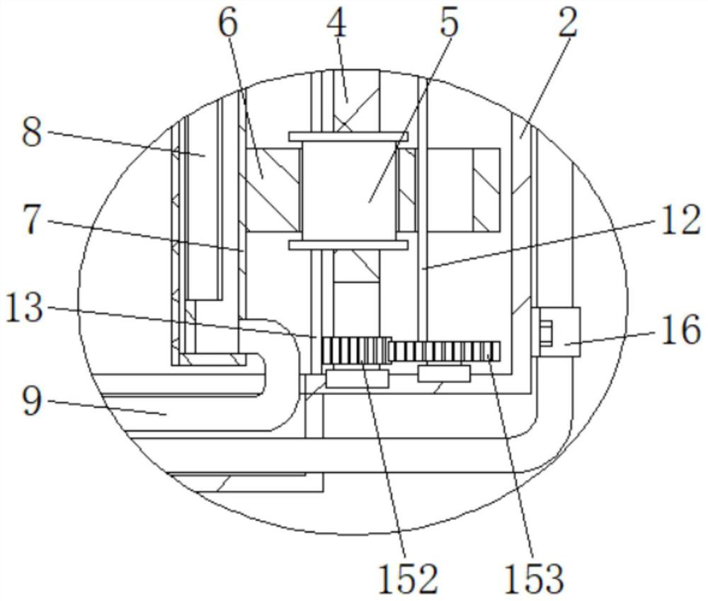
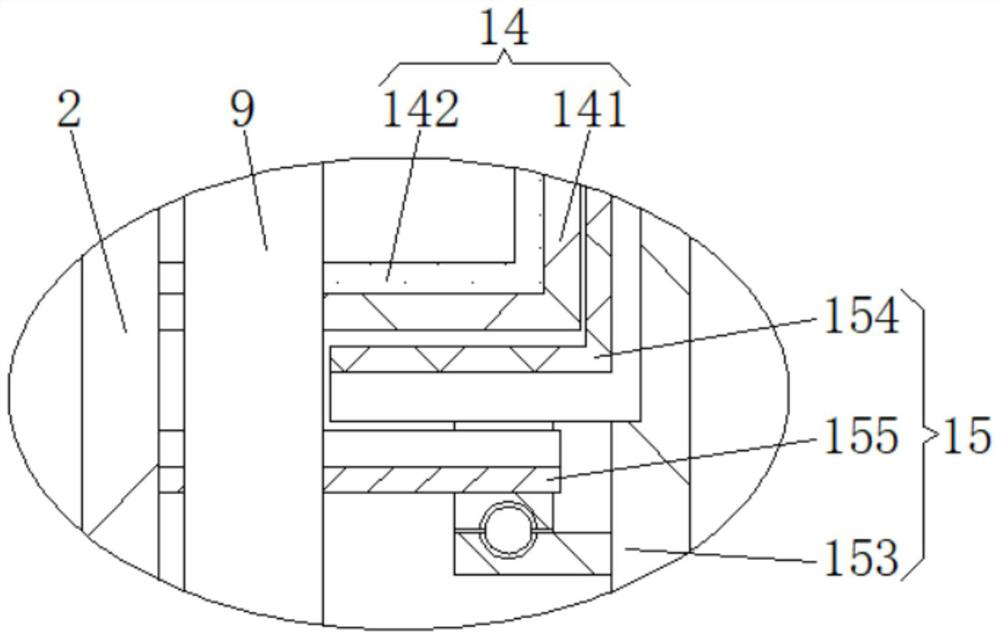
[0031] Such as Figure 1 to Figure 6 As shown, the present invention provides a power distribution cabinet that can expand the heat dissipation range and a method for expanding heat dissipation, including a power distribution cabinet body 1, a trapezoidal box 2 connected to the right side of the power distribution cabinet body 1, and the top of the trapezoidal box 2 is fixed Connected with a motor 3, the bottom of the motor 3 penetrates into the interior of th...


PUM


Abstract

The invention discloses a power distribution cabinet capable of expanding a heat dissipation range and a heat dissipation expanding method, the power distribution cabinet comprises a power distribution cabinet body, the right side of the power distribution cabinet body is communicated with a trapezoidal box, the top of the trapezoidal box is fixedly connected with a motor, the bottom end of the motor penetrates into the trapezoidal box and is fixedly connected with a reciprocating screw rod, and the surface of the reciprocating screw rod is slidably connected with a transmission sleeve through a connecting rod. The motor drives the rotating sleeve and the mounting sleeve to move up and down through the reciprocating screw rod and the transmission sleeve, the vertical heat dissipation range of the axial flow fan is increased, then the reciprocating screw rod and the first gear drive the sliding rod to rotate through the second gear, and the sliding rod drives the rotating sleeve to swing back and forth with the reciprocating screw rod as the center, t-.herefore, the power distribution cabinet has the advantage of being capable of expanding the heat dissipation range, and solves the problems that an existing power distribution cabinet only carries out heat dissipation through a single fixed heat dissipation fan, the heat dissipation range is small, the heat dissipation efficiency is affected, and effective heat dissipation cannot be carried out on different positions.

Description

technical field [0001] The invention relates to the technical field of power distribution cabinets, in particular to a power distribution cabinet capable of expanding the heat dissipation range and a method for expanding heat dissipation. Background technique [0002] Power distribution cabinets are divided into power distribution cabinets, lighting distribution cabinets, and metering cabinets. They are the final equipment of the power distribution system. A single fixed heat dissipation fan performs heat dissipation, and the heat dissipation range is small, which affects the heat dissipation efficiency and cannot effectively dissipate heat in different positions. Contents of the invention [0003] In order to solve the problems raised in the above-mentioned background technology, the object of the present invention is to provide a power distribution cabinet that can expand the heat dissipation range and a method for expanding heat dissipation, which has the advantage of e...

Claims


Application Information

Patent Timeline
Patent Type & Authority Applications(China)
IPC IPC(8): H02B1/56H02B1/32H02B1/28H02B1/30B01D46/10B01D46/00B01D53/26B08B1/04B08B1/00
CPCH02B1/565H02B1/32H02B1/28H02B1/30B01D46/10B01D46/0027B01D53/26B08B1/12B08B1/32
Inventor 朱慧
Owner 宁波佳慧电气实业有限公司
Learn More