Electric power cabinet with good damping effect

A shock-absorbing effect and power cabinet technology, applied in the field of electric power, can solve problems such as vibration, adjustment, and unfavorable service life of the power cabinet, and achieve the effect of improving heat dissipation efficiency and expanding the heat dissipation range

Inactive Publication Date: 2021-02-19
阳四花
View PDF0 Cites 2 Cited by
  • Summary
  • Abstract
  • Description
  • Claims
  • Application Information

AI Technical Summary

Problems solved by technology

[0003] The internal equipment of the power cabinet will vibrate when it is working, or it will vibrate even more when it is impacted by the outside, which is not good for the service life of the power cabinet. Adjustment of shock absorption effect

Method used


Image

  • Electric power cabinet with good damping effect
  • Electric power cabinet with good damping effect

Examples


Embodiment 1

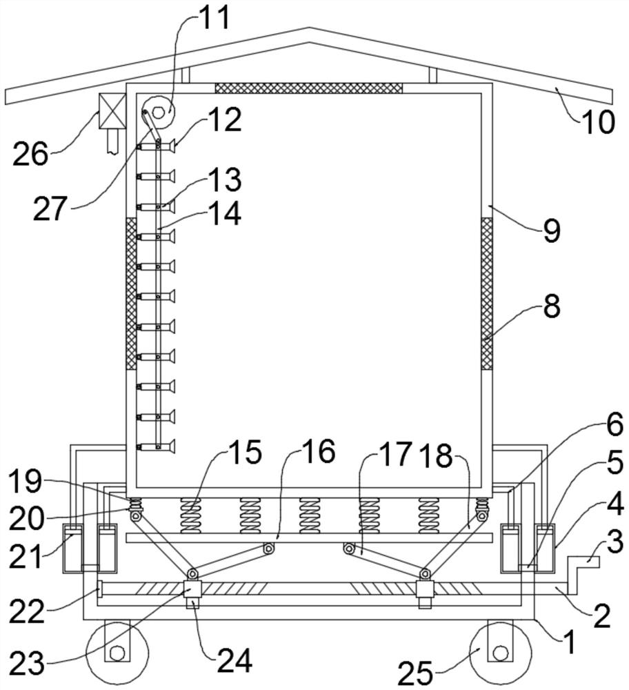
[0024] see figure 1 , in an embodiment of the present invention, a power cabinet with good shock absorption effect includes a cabinet body 9, the cabinet body 9 is installed in the installation groove opened on the base 1, and a rain shield is fixedly installed on the top of the cabinet body 9 10. The rain shield 10 is preferably in the shape of an umbrella, and dust-proof nets 8 are installed on both side walls and the top of the cabinet body 9 to facilitate heat dissipation in the cabinet body 9. In this embodiment, the dust-proof nets 8 are preferably screwed Installed on the cabinet 9, the bottom of the base 1 is evenly and symmetrically fixed with rollers 25, the rollers 25 are self-locking rollers, which facilitate the movement of the device, and a shock absorbing unit is connected between the cabinet 9 and the base 1. The damping unit includes a two-way screw rod 2, an internal thread sleeve 23, a first connecting rod 17, a second connecting rod 18, a mounting plate 16,...

Embodiment 2

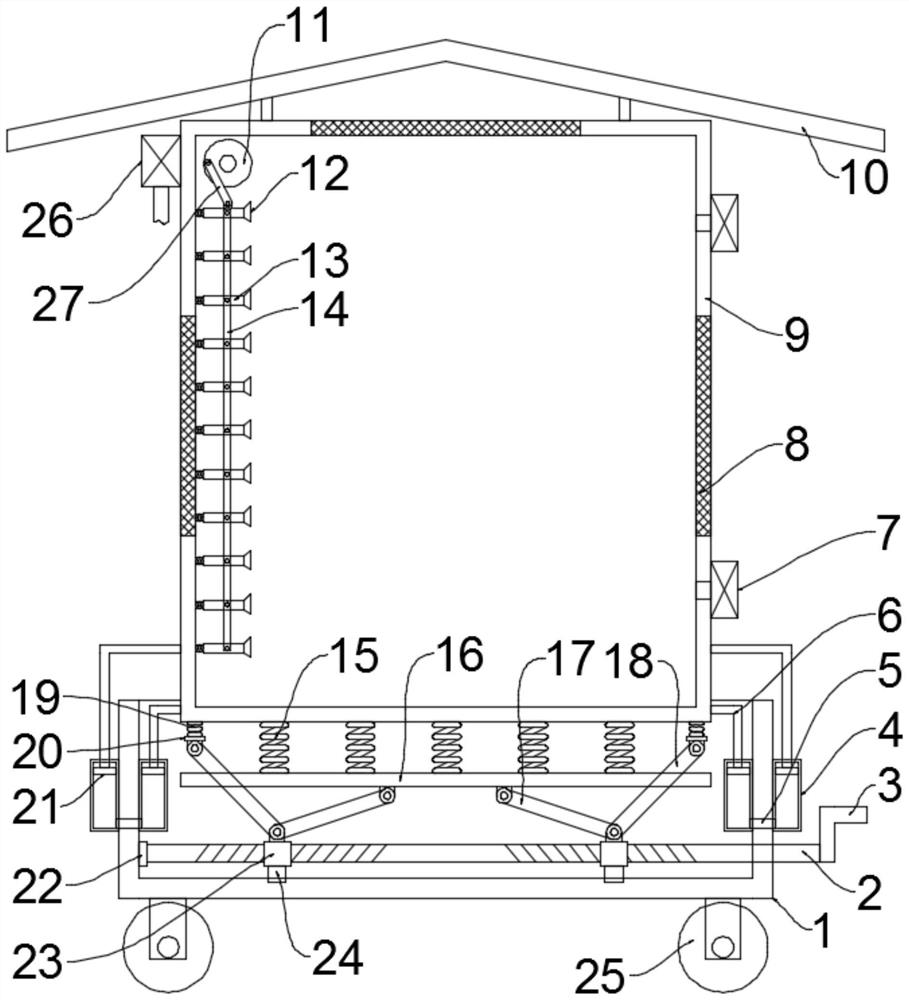
[0028] see figure 2 The difference between this embodiment of the present invention and Embodiment 1 is that an exhaust fan 7 is installed on the side wall of the cabinet 9 away from the nozzle 12, and the exhaust fan 7 is used to extract the hot air in the cabinet 9 to further improve the heat dissipation efficiency .

[0029]The working principle of the present invention is: when working, the compression spring 15 can play the effect of shock absorption, and the two-way screw mandrel 2 is driven to rotate by the rocking handle 3, and the two-way screw mandrel 2 drives two internally threaded sleeves 23 to approach each other, and the internally threaded sleeves 23 The first connecting rod 17 drives the mounting plate 16 to move upwards to adjust the compression of the compression spring 15. At the same time, the internal thread sleeve 23 pulls the tension spring 19 through the second connecting rod 18, and the tension spring 19 pulls the cabinet body 9 downward, further Ad...


PUM


Abstract

The invention discloses an electric power cabinet with a good damping effect, which comprises a cabinet body, the cabinet body is installed in a mounting groove formed in a base, a damping unit is connected between the cabinet body and the base, and the damping unit comprises a two-way lead screw, internal thread sleeves, a first connecting rod, a second connecting rod, a mounting plate, a compression spring and an extension spring. The two-way lead screw is horizontally and rotatably mounted in the mounting groove of the base, the electric power cabinet also comprises a heat dissipation unitwhich comprises a heat dissipation fan, a motor, a turntable, a third connecting rod and a nozzle, the damping unit is arranged, the two-way lead screw drives two internal thread sleeves to be close to each other, and the internal thread sleeves drive the mounting plate to move upwards through the first connecting rod. The compression amount of the compression spring is adjusted, the internal thread sleeves pull the extension spring through the second connecting rod, the extension spring pulls the cabinet body downwards, the distance between the cabinet body and the mounting plate is further adjusted, the damping force of the compression spring is adjusted, the purpose of adjusting the damping effect is achieved, the heat dissipation unit is arranged, the heat dissipation range is enlarged, and the heat dissipation efficiency is improved.

Description

technical field [0001] The invention relates to the technical field of electric power, in particular to a power cabinet with good shock absorption effect. Background technique [0002] Power cabinets (boxes) are divided into power power cabinets (boxes), lighting power cabinets (boxes), and metering cabinets (boxes), which are the final equipment of the power distribution system. The power cabinet is a general term for the motor control center. The power cabinet is used in the occasions where the load is relatively scattered and there are few circuits; the motor control center is used in the occasions where the load is concentrated and there are many circuits. They distribute the electric energy of a certain circuit of the upper-level power distribution equipment to the nearest load. This level of equipment shall provide protection, monitoring and control of the load. [0003] The internal equipment of the power cabinet will vibrate when it is working, or it will vibrate ...

Claims


Application Information

Patent Timeline
Patent Type & Authority Applications(China)
IPC IPC(8): H02B1/54H02B1/50H02B1/30H02B1/56
CPCH02B1/30H02B1/303H02B1/50H02B1/54H02B1/565
Inventor 阳四花
Owner 阳四花
Why Eureka
Try Eureka