Fixation components for implantable medical devices

A fixed-part, fixed-ground technology used in therapy, electrotherapy, internal electrodes, etc.

Pending Publication Date: 2021-12-07
MEDTRONIC INC
View PDF2 Cites 0 Cited by
  • Summary
  • Abstract
  • Description
  • Claims
  • Application Information

AI Technical Summary

Problems solved by technology

Thin leads may involve mechanical and / or MRI compatibility issues

Method used


Image

  • Fixation components for implantable medical devices
  • Fixation components for implantable medical devices
  • Fixation components for implantable medical devices

Examples


Embodiment Construction

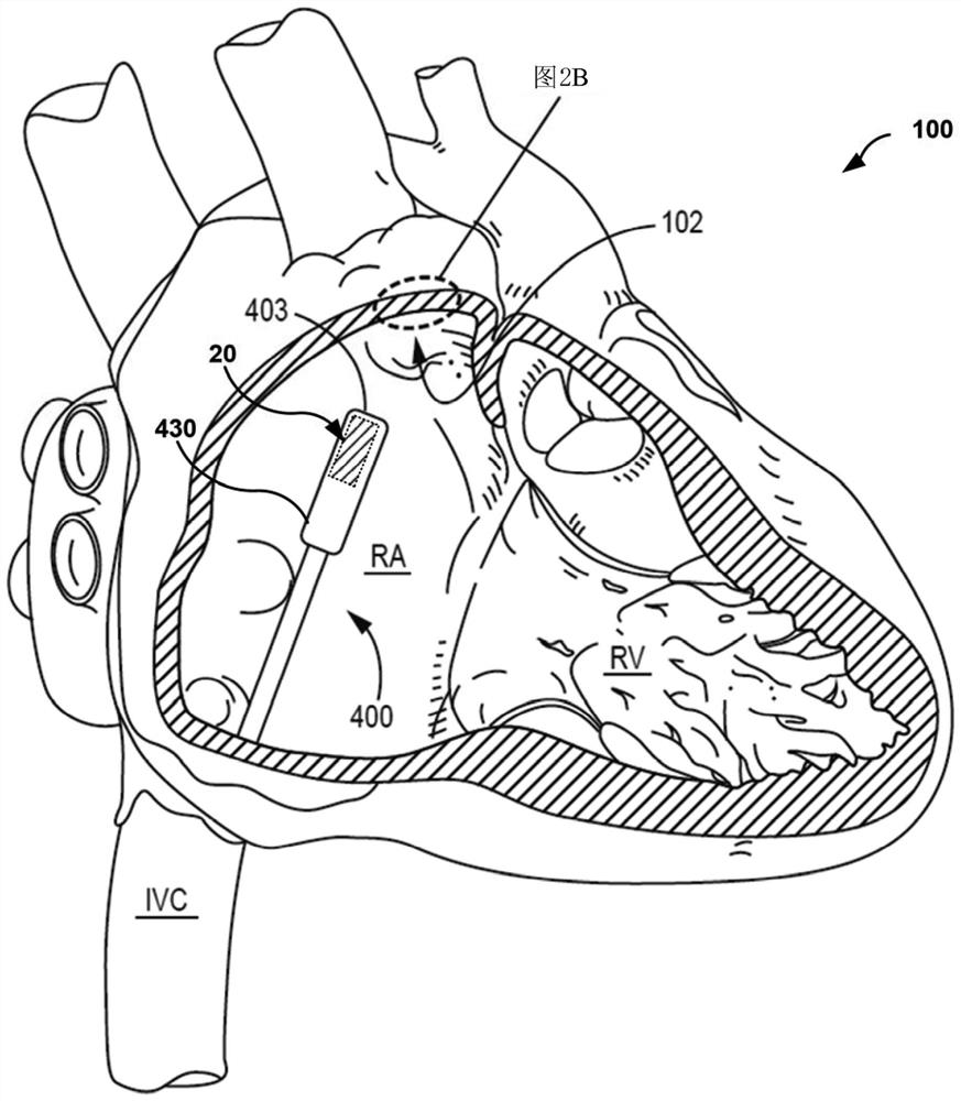
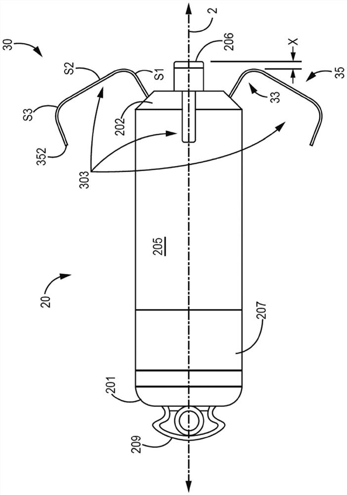
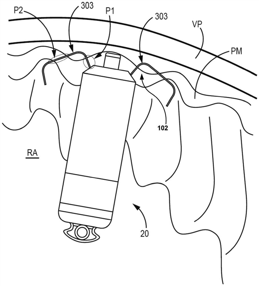
[0025]The present disclosure describes IMD fixation components having improved flexibility, fixation, or both, to facilitate implantation of IMDs, such as relatively compact IMDs. An example fixation component for an IMD may include a base and a plurality of teeth. The plurality of teeth are configured to deploy at a target deployment stiffness to engage tissue at a target implant site while maintaining a target deflection stiffness after deployment to enable visualization of engagement with tissue (eg, via fluoroscopy). The base can define a longitudinal axis of the fixation component, eg, the proximal and distal ends of the IMD can be aligned along the longitudinal axis. The base can be fixedly attached to the IMD near the distal end of the IMD. A plurality of teeth may be spaced from each other around the periphery of the distal end of the IMD and extend from the base. The shape of each respective tooth of the plurality of teeth may be selected to control each of the targ...


PUM

PropertyMeasurementUnit
Lengthaaaaaaaaaa
Lengthaaaaaaaaaa
Widthaaaaaaaaaa

Abstract

An example fixation component for an implantable medical device (IMD) includes a base and a plurality of tines configured be deployed with a target deployment stiffness to engage tissue a target implant site while maintaining a target deflection stiffness after deployment. The base defines a longitudinal axis of the fixation component and is fixedly attached near the distal end of the IMD. Each tine is spaced apart from one another around a perimeter of the distal end of the IMD and extend from the base. A shape of each tine is selected to control each of the target deployment stiffness and target deflection stiffness.

Description

technical field [0001] The present disclosure relates to medical device systems, such as relatively compact implantable medical devices and associated fixation components. Background technique [0002] In some examples, an implantable cardiac pacemaker includes a pulse generator device to which one or more flexible elongated leads are coupled. The pulse generator device may be implanted in a subcutaneous pocket remote from the heart, and each of the one or more leads extend from the device to a corresponding electrode coupled to the lead and located on the endocardium or The pacing site of the epicardium. Thin leads may involve mechanical and / or MRI compatibility issues. Relatively compact implantable medical devices (IMDs) have been developed that are fully contained within relatively compact packages configured to be implanted, for example, within a chamber of the heart proximate to a pacing site. Contents of the invention [0003] The present disclosure describes IMD...

Claims


Application Information

Patent Timeline
IPC IPC(8): A61N1/05A61N1/372A61N1/375
CPCA61N1/0573A61N1/37205A61N1/37518A61N1/3756B21D39/02A61N1/059
Inventor 陈鑫V·格鲁巴克B·P·克林K·希尔皮什M·D·伊根
Owner MEDTRONIC INC
Why Eureka
Try Eureka