Full-automatic storage battery joint continuous punch forming equipment and production process

A stamping and forming, battery technology, applied in the direction of forming tools, metal processing equipment, manufacturing tools, etc., can solve the problems of high labor cost and maintenance cost, multiple labor and machines, etc., to reduce handling steps, speed up production efficiency, production efficiency improved effect

Pending Publication Date: 2021-12-10
WENZHOU FENGDI CONNECTOR
View PDF10 Cites 0 Cited by
  • Summary
  • Abstract
  • Description
  • Claims
  • Application Information

AI Technical Summary

Problems solved by technology

[0002] Car batteries need to be connected through connectors when they are in use. There are various types and shapes of battery connectors. The traditional processing of battery connectors requires copper sheet cutting, copper sheet punching, edge bending and shaping, and socket hole warping. Pressing process, each process requires workers to use a piece of equipment to complete each process, and at the same time, after each process is completed, it needs to be manually transported to the next process, for example, a piece of equipment is cut into copper sheets of a certain specification, and then transported to another production line Drilling and plasticity are carried out on the top of the copper strip. The Chinese invention patent CN201810835839.5 discloses a copper sheet stamping and forming mechanism. The push rod of the push rod is quickly pushed down to carry out stamping and forming. After the lower mold is lifted back to its position, it is convenient to unload the material. This invention patent is only a process in the metal stamping and forming processing equipment, and it needs to be processed step by step by other equipment. The process requires more labor and machines, so labor costs and machine use and maintenance costs are extremely high

Method used


Image

  • Full-automatic storage battery joint continuous punch forming equipment and production process
  • Full-automatic storage battery joint continuous punch forming equipment and production process
  • Full-automatic storage battery joint continuous punch forming equipment and production process

Examples


Embodiment Construction

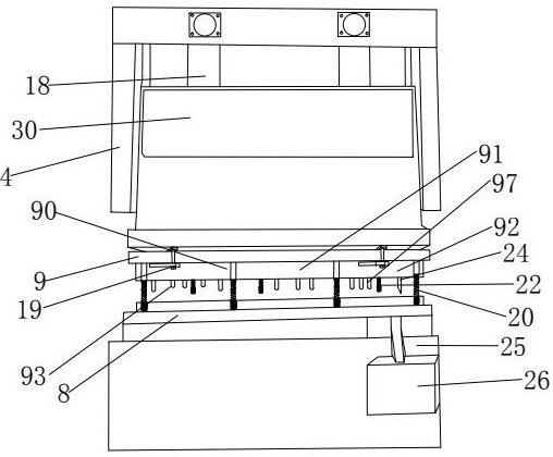
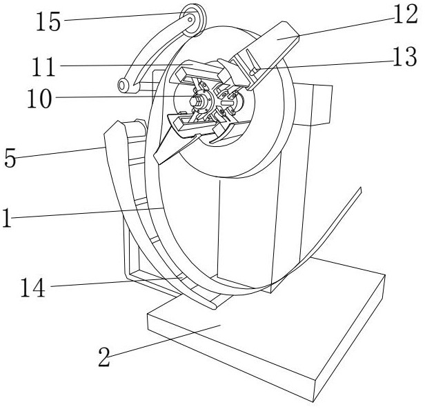
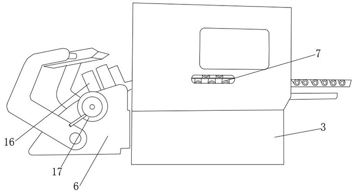
[0034] Such as Figure 1-10 As shown, a fully automatic continuous stamping and forming equipment for battery joints, including a discharge rack 2 for placing copper sheets 1, a shaping machine 3 for shaping copper sheets 1, and a battery joint punching machine 4, is characterized in that the A copper sheet 1 is placed on the discharge rack 2 through a reel 10, and the copper sheet 1 is guided and transported along the guide frame 5 on the lower side of the discharge rack 2, and the copper sheet 1 is transported to the limit frame 6 on the side of the shaping machine 3, and the shaping Inside the machine 3 are provided with several rollers 7 for extruding and conveying the copper sheet 1, the copper sheet 1 is arranged on the lower die 8 of the punching machine 4, and the upper die 9 of the punching machine 4 is arranged above the copper sheet 1, and the discharge rack 2 is used to transport the copper sheet 1 smoothly. The feeding rack 2 transports the copper sheet 1 to the l...


PUM


Abstract

The invention discloses full-automatic storage battery joint continuous punch forming equipment and a production process. The full-automatic storage battery joint continuous punch forming equipment comprises a material placing frame for placing a copper sheet, a shaping machine for shaping the copper sheet and a storage battery joint punching machine, and is characterized in that the copper sheet is placed on the material placing frame through a reel, and the copper sheet is guided and conveyed along a guide frame on the lower side of the material placing frame; the copper sheet is conveyed to a limiting frame on one side of the shaping machine, a plurality of rollers used for extruding and conveying the copper sheet are arranged in the shaping machine, the copper sheet is arranged on a lower die of the punching machine, and an upper die of the punching machine is arranged above the copper sheet. The copper sheets are conveyed step by step through full-automatic production equipment, the copper sheets are gradually and continuously machined into the storage battery joints through the punching machine, the number of machines is reduced, meanwhile, the carrying step among a plurality of working procedures is reduced, only one operator is needed to carry out copper sheet discharging and machine nursing, and the cost is effectively reduced.

Description

technical field [0001] The invention relates to the field of automotive battery parts, in particular to a fully automatic battery connector continuous stamping forming equipment and production process. Background technique [0002] Car batteries need to be connected through connectors when they are in use. There are various types and shapes of battery connectors. The traditional processing of battery connectors requires copper sheet cutting, copper sheet punching, edge bending and shaping, and socket hole warping. Pressing process, each process requires workers to use a piece of equipment to complete each process, and at the same time, after each process is completed, it needs to be manually transported to the next process, for example, a piece of equipment is cut into copper sheets of a certain specification, and then transported to another production line Drilling and plasticity are carried out on the top of the copper strip. The Chinese invention patent CN201810835839.5 d...

Claims


Application Information

Patent Timeline
Patent Type & Authority Applications(China)
IPC IPC(8): B21D53/36B21D35/00B21D37/08
CPCB21D53/36B21D35/002B21D37/08
Inventor 邱昌甲赵奎
Owner WENZHOU FENGDI CONNECTOR
Why Eureka
Try Eureka