
Foundation pit protection device for highway engineering

A protective device and engineering technology, applied in infrastructure engineering, excavation, construction, etc., can solve the problems of poor practicability, poor protection, and inability to form a whole, so as to ensure effective protection, eliminate safety hazards, and ensure stability.

Pending Publication Date: 2021-12-10
安徽丰林建设工程有限公司
View PDF9 Cites 0 Cited by
  • Summary
  • Abstract
  • Description
  • Claims
  • Application Information

AI Technical Summary

Problems solved by technology

[0003] In the prior art, the protection of the foundation pit is mostly to insert the upper limit plate evenly around the foundation pit for support and protection. The limit plate exists alone and cannot form an integrity with each other, so the protection is poor; and the limit plate inserts After being connected, the force of the limiting plate on the side wall of the foundation pit cannot be changed, which does not meet the actual construction requirements and has poor practicability

Method used


Image

  • Foundation pit protection device for highway engineering
  • Foundation pit protection device for highway engineering
  • Foundation pit protection device for highway engineering

Examples


Embodiment 1

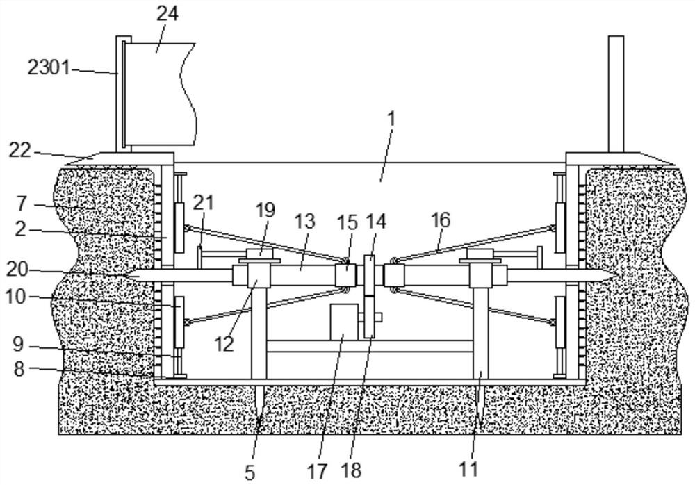
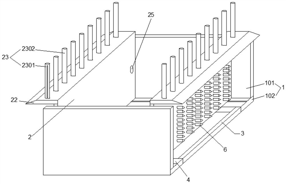
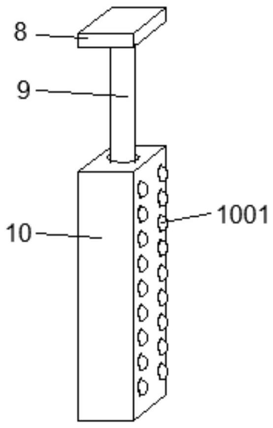
[0030] A foundation pit protection device for highway engineering, including a fixed plate 1, a moving plate 2 and a control mechanism, the fixed plate 1 is provided with two pieces, and the front and rear are symmetrically arranged, wherein the fixed plate 1 is composed of a vertical plate 101 and a horizontal plate 102 L Shaped structure, between 102 horizontal plates is connected with fixed rod 3, and fixed rod 3 is positioned at the left and right ends of horizontal plate 102, can combine two fixed plates 1 into a whole by the connection of fixed rod 3. The upper side of horizontal plate 102 is provided with chute 4, is provided with slide block in chute 4, and the bottom surface of horizontal plate 102 is vertically connected with the first inserting rod 5, and the bottom end of the first inserting rod 5 is set as conical, the second An insertion rod 5 can be inserted into the bottom surface of the foundation pit 7 to ensure the stability of the fixing plate 1 placed in th...

Embodiment 2

[0035] The difference from Embodiment 1 is that an electric push rod 19 is provided above the bearing 12, and a through hole 1301 is provided on the end surface of the two-way screw rod 13, and a third inserting rod 20 is movably inserted in the through hole 1301, and the third inserting rod 20 is movably inserted into the through hole 1301. The end portion of bar 20 is made as conical, and the upper side of the 3rd inserting bar 20 is vertically connected with connecting piece 21, and connecting piece 21 is fixedly connected with the free end of electric pushrod 19, offers on the moving plate 2 and the 3rd in addition. The insertion hole 25 corresponds to the insertion rod 20 . After the first insertion rod 5 can be inserted in the bottom surface of the foundation pit 7, the electric push rod 19 can be started to extend the free end, and the third insertion rod 20 can pass through the jack 25 and be inserted into the side wall of the foundation pit 7, which limits the The amp...

Embodiment 3

[0037] Different from the above-mentioned embodiment, the top of the moving plate 2 is horizontally provided with an auxiliary plate 22, the moving plate 2 and the auxiliary plate 22 form an L-shaped structure, and the upper side of the auxiliary plate 22 is linearly provided with several protective rods 23, and the lower side Rollers are provided, wherein the protection bar 23 can form a fence to prevent pedestrians or construction workers from falling into the foundation pit 7 without paying attention, and the rollers can reduce the friction force when the auxiliary plate 22 contacts the ground to ensure the movement of the plate. 2 moving effects. Wherein the protective rod 23 is divided into a common rod 2302 and a hollow rod 2301, the hollow rod 2301 is located at the outermost side, the side wall of the hollow rod 2301 is provided with a cleaning rod, the inside of the hollow rod 2301 is provided with a rotating shaft, and a protective cloth is wound on the rotating shaft...


PUM


Abstract

The invention relates to the technical field of highway engineering, in particular to a foundation pit protection device for highway engineering. The foundation pit protection device comprises fixed plates, movable plates and a control mechanism; the two fixed plates are symmetrically arranged front and back, each fixed plate is of an L-shaped structure composed of a vertical plate and a horizontal plate, a fixed rod is connected between the horizontal plates, and the fixed rods are located at the left and right ends of the horizontal plates; and the two movable plates are symmetrically arranged left and right, the bottom ends of the movable plates are slidably connected to the horizontal plates, extrusion assemblies are arranged on the opposite faces of the two movable plates, and the control mechanism comprises a mounting frame, a two-way lead screw and a motor. According to the foundation pit protection device, a frame structure consisting of the fixed plates and the movable plates is adopted to support the side wall of the foundation pit, the effectiveness and stability of protection can be improved, in addition, the positions of the movable plates can be adjusted through the control mechanism, so that the acting force between the movable plates and the side wall of the foundation pit is changed, the construction requirement is met, and practicability is improved.

Description

technical field [0001] The invention relates to the technical field of highway engineering, in particular to a foundation pit protection device for highway engineering. Background technique [0002] Highway engineering refers to the investigation, measurement, design, construction, maintenance and management of highway structures. . When carrying out road construction, it is often necessary to excavate the foundation pit. The foundation pit is actually a soil pit excavated at the foundation design position according to the base elevation and foundation plane size. The inside of the pit shall be protected to prevent the interior of the foundation pit from collapsing and causing harm to the workers at the bottom of the foundation pit. [0003] In the prior art, the protection of the foundation pit is mostly to insert the upper limit plate evenly around the foundation pit for support and protection. The limit plate exists alone and cannot form an integrity with each other, so...

Claims


Application Information

Patent Timeline
IPC IPC(8): E02D17/04
CPCE02D17/04
Inventor 胡朝鲜
Owner 安徽丰林建设工程有限公司
Learn More