
Water drive tank and water purifier

A water purifier and water flooding technology, applied in water/sewage treatment, water/sewage multi-stage treatment, water/sludge/sewage treatment, etc., can solve the problem of occupying space, low safety factor, and practical utilization of water storage Insufficient efficiency and other problems, to achieve the effect of increasing the utilization rate of water storage space and reducing the risk of barrel explosion

Pending Publication Date: 2019-12-27
NINGBO PUER WATER PURIFICATION TECH CO LTD
View PDF0 Cites 0 Cited by
  • Summary
  • Abstract
  • Description
  • Claims
  • Application Information

AI Technical Summary

Problems solved by technology

Its disadvantages mainly include: the conventional small flux is equipped with an external air drive pressure tank, which takes up space; when the air drive pressure tank is configured, the water flow rate tends to decline and the actual utilization rate of the water storage is insufficient; when the air drive pressure tank is configured, it is safe. The coefficient is low, and there is a hidden danger of "bucket explosion", that is, the possibility of gas expansion

Method used


Image

  • Water drive tank and water purifier
  • Water drive tank and water purifier
  • Water drive tank and water purifier

Examples


Embodiment 1

[0043] See attached figure 1 And attached figure 2 , The water flooding tank provided in Embodiment 1 of the present invention includes an inner tank and an outer tank. The inner tank is contained inside the outer tank, and a cavity is formed between the tank body of the inner tank and the tank body of the outer tank, and the inner tank and the cavity can communicate with the outside respectively. Water can exert a squeezing force between the inner tank and the cavity, wherein, when the water pressure inside the inner tank is greater than the water pressure in the cavity, the inner tank will When the volume of the cavity increases, the water in the cavity is squeezed out; when the water pressure inside the cavity is greater than the hydraulic pressure of the inner tank, the water in the cavity passes through the tank of the inner tank The body exerts a squeezing force to squeeze out the water inside the inner tank.

[0044] In the application process of the water flooding ...

Embodiment 2

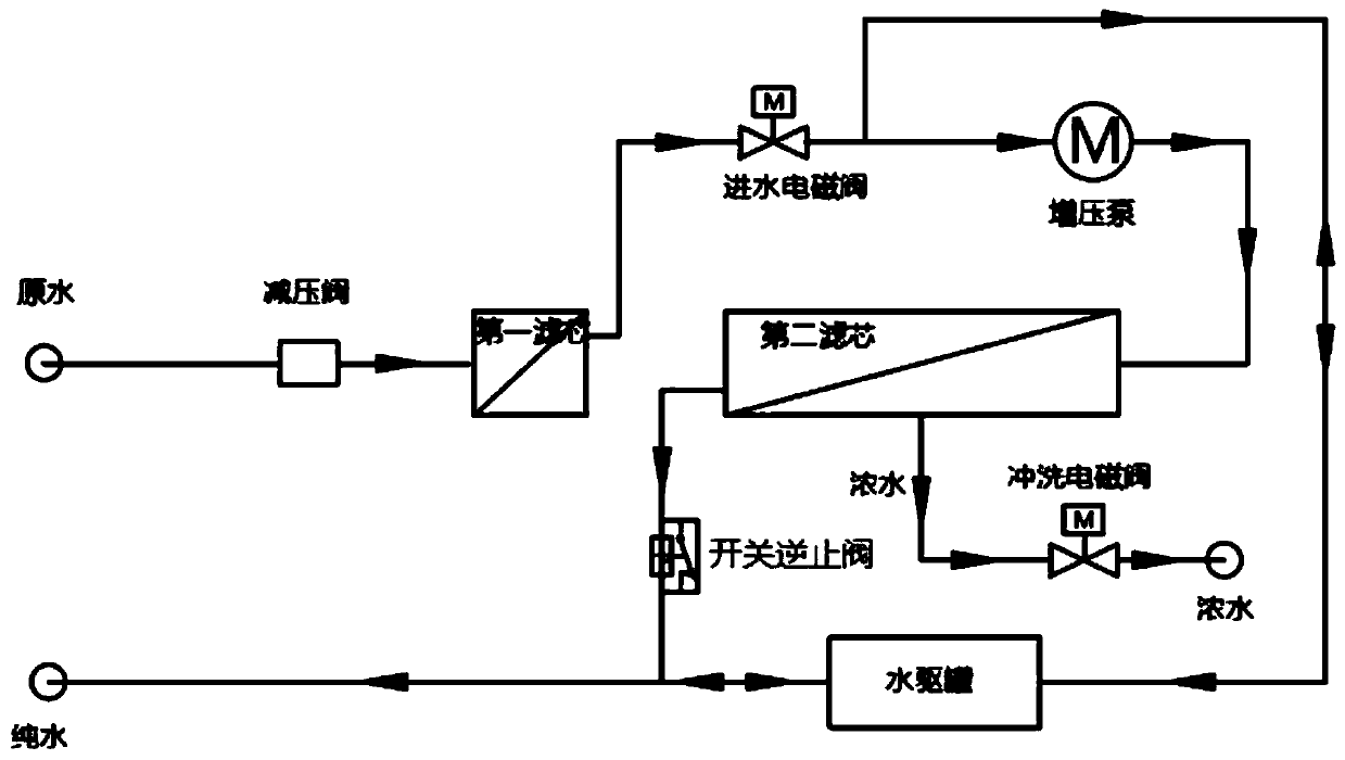
[0047] See attached image 3 , The water purifier provided by Embodiment 2 of the present invention includes a pressure reducing valve, a first filter element, a water inlet valve, a booster pump, a second filter element, a switch check valve, a flushing valve and the water flooding tank provided by the present invention. The booster pump, the retention port of the second filter element, and the check valve are connected in series to form a first series waterway; the water drive tank is connected in parallel with the first series waterway to form a parallel waterway; The pressure valve, the first filter element, the water inlet solenoid valve, and the parallel waterway are connected in series to form a water-making passage; the flushing valve is connected to the filtering port of the second filter element; raw water passes through the water-making The channel produces water and discharges the pure water through the water drive tank, and the filtered concentrated water is disch...


PUM


Abstract

The invention discloses a water drive tank and a water purifier, and belongs to the technical field of water treatment equipment. The water drive tank comprises an inner tank and an outer tank, the inner tank is contained in the outer tank, a cavity is formed between a tank body of the inner tank and a tank body of the outer tank, and the inner tank and the cavity can be communicated with the exterior respectively; water can mutually apply extrusion acting force between the inner tank and the cavity, so that when the water pressure in the inner tank is greater than that of the cavity, the inner tank is increased along with the increase of the volume of the water in the inner tank to push out the water in the cavity; and when the water pressure in the cavity is greater than the water pressure of the inner tank, the water in the cavity extrudes out the water in the inner tank by applying an extrusion acting force to the tank body of the inner tank. The utilization rate of water storage space can be increased, and the risk of barrel explosion is reduced.

Description

technical field [0001] The invention relates to the technical field of water treatment equipment, in particular to a water drive tank and a water purifier. Background technique [0002] The water purifier in the prior art usually uses a gas-driven pressure tank, and when the tank is empty, the pressure in the air bag is about 0.5kg. After the pure water is slowly poured into the barrel, the air in the airbag is compressed, and the air pressure gradually increases until the pressure of the airbag reaches the set pressure of the high pressure switch, and the machine stops. Its disadvantages mainly include: the conventional small flux is equipped with an external air drive pressure tank, which takes up space; when the air drive pressure tank is configured, the water flow rate tends to decline and the actual utilization rate of the water storage is insufficient; when the air drive pressure tank is configured, it is safe. The coefficient is low, and there is a hidden danger of "...

Claims


Application Information

Patent Timeline
IPC IPC(8): C02F9/02F16J12/00C02F103/04
CPCC02F1/441C02F1/001F16J12/00C02F2103/02
Inventor 邹浩陈笃力
Owner NINGBO PUER WATER PURIFICATION TECH CO LTD
Learn More