Paintball loader

a paintball loader and loader technology, applied in the field of paintball loaders, can solve the problems of high fire rate, inability to achieve, and insatiable feeding of paintballs only by gravity force,

Active Publication Date: 2006-04-27
DYE PRECISION
View PDF12 Cites 66 Cited by
  • Summary
  • Abstract
  • Description
  • Claims
  • Application Information

AI Technical Summary

Benefits of technology

[0011] An object of the present invention is to provide an improved paintball loader which eliminates at least some of the above problems.

Problems solved by technology

The main reason to provide a feeding mechanism is that the feeding of paintballs only by force of gravity not works satisfactory.
Firstly a high rate of fire, which is essential for the player, can not be achieved merely with a gravity driven feeding.
Secondly the force of gravity only works when the marker is held in an upright or close to upright position, and consequently there is no feeding at all when the marker is tilted in certain angles since the paintballs then do not fall into the outlet tube.
When the player starts firing, the feeding of the paintballs through the outlet tube is initially very slow since only the force of gravity or any pressure between the stuck paintballs causes them to move into the marker.
However, the rate of balls being forced down the outlet by the rotor is still not satisfactory.
Further, the rotor inertia causes a delay before the drive motor reaches its normal speed, thus reducing the rate of paintballs even further in the beginning of a firing burst.
Although a high feeding speed is desirable, the resulting high stresses on the ball may cause problems with breaking paintballs which leads to fluid leakage in the marker or in the paintball loader itself.
Such breakages causes problems for, or even a stop of the feeding of the paintballs.

Method used


Image

  • Paintball loader
  • Paintball loader
  • Paintball loader

Examples


Embodiment Construction

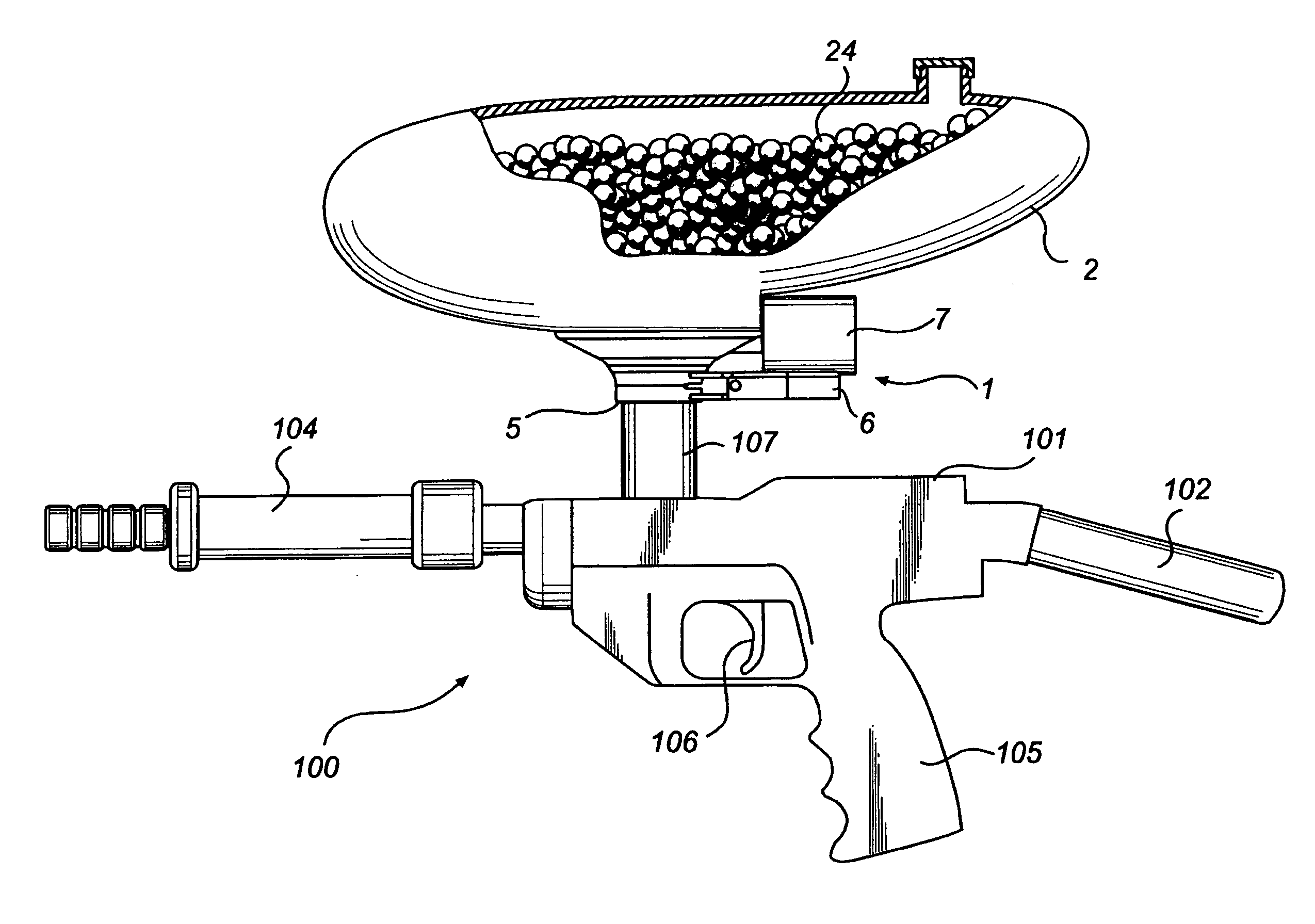
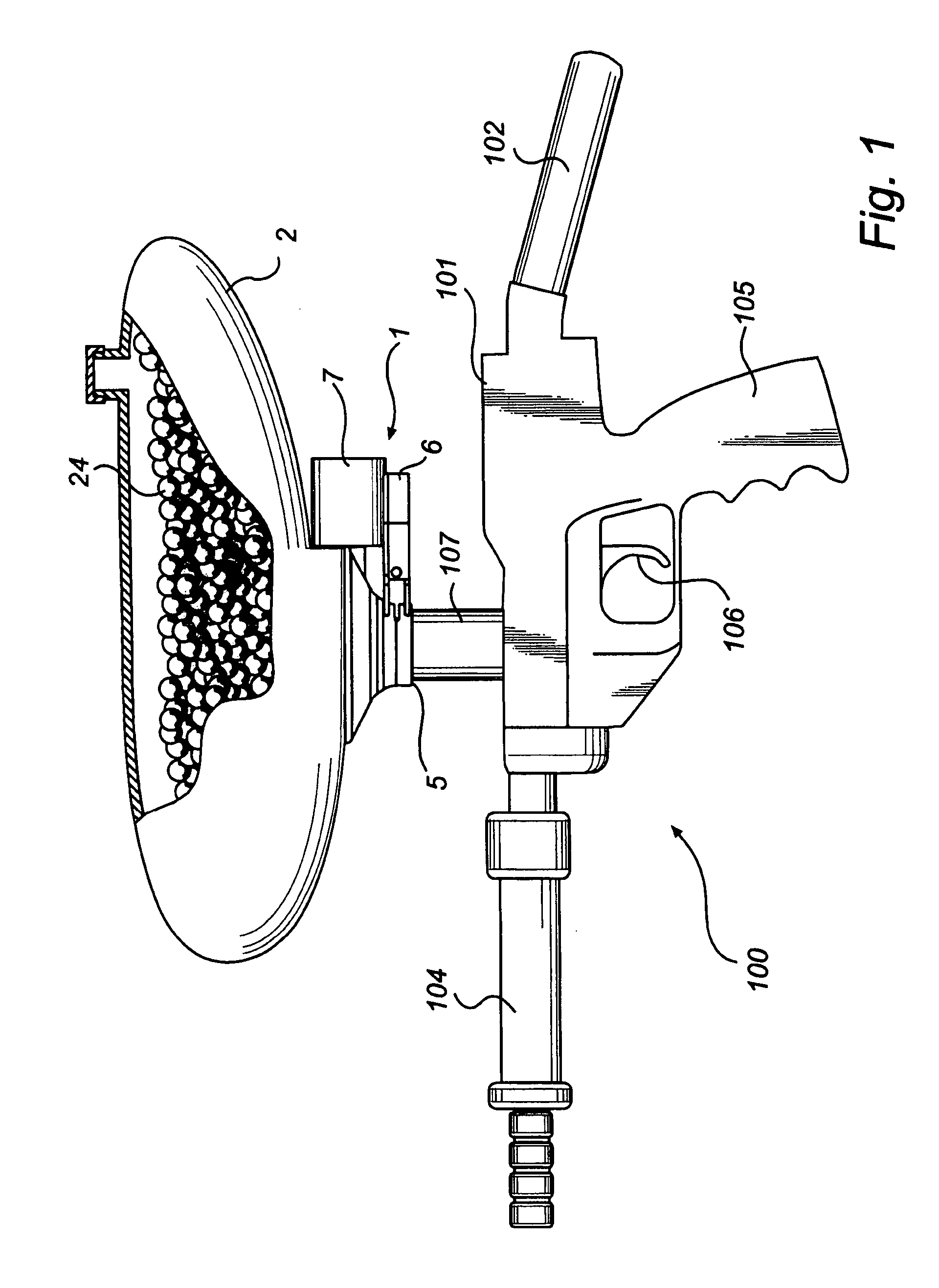
[0032]FIG. 1 is a schematic side view of a paintball marker 100 equipped with a paintball loader 1 according to an embodiment of the invention. The paintball loader 1 is attached to the lower part of a paintball container 2, and has a central outlet 5 leading out of the container 2.

[0033] The paintball loader 1 is attached to the top side of a the paintball marker 100, which is illustrated as an example only. The paintball marker 100 includes a marker body 101 and a compressed gas cylinder 102 which typically is arranged to the rear end of the paintball marker 100. The paintball marker 100 further comprises a barrel 104 and a handgrip 105. The paintball marker 100 also comprises a trigger 106 and an inlet tube 107 which is connected to the central outlet 5 of the paintball loader 1. The inlet tube 107 receives paintballs from the paintball loader 1 and leads to a firing chamber in the interior of the marker body 101.

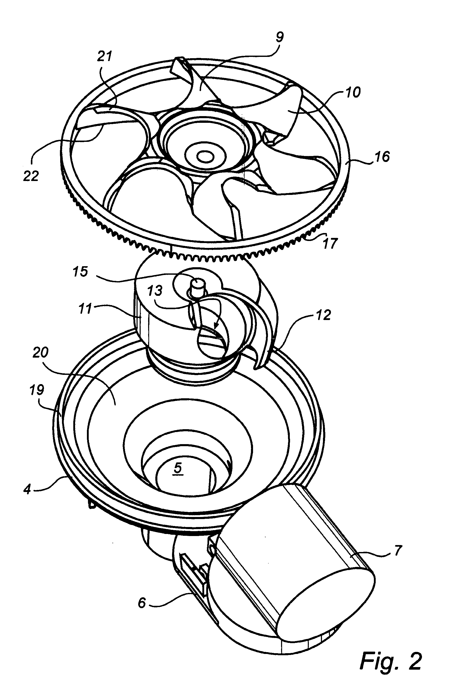
[0034]FIG. 2 is an exploded schematic perspective view of a paint...


PUM


Abstract

A paintball loader, more specifically a paintball loader which rapidly and forcibly feeds paintballs to a paintball marker, comprises a rotor body (9) having at least one rotor fin (10), and a drive motor (7) for rotating said rotor body (9) in a first direction. The paintball loader has a central outlet (5) located radially inwards of the tip of the rotor fin (10) and an abutment body (11) arranged to interact with said at least one rotor fin (10). When the rotor body (9) is rotated, a paintball (24), located in a space (14) formed between said at least one rotor fin (10) and said abutment body (11), is pushed out of said paintball loader (1) through the central outlet (5).

Description

PRIORITY STATEMENT [0001] This U.S. non-provisional application claims benefit of priority under 35 U.S.C. §119 from European Patent Application No. 04025414.6 filed on Oct. 26, 2004, the entire contents of which are incorporated herein by reference. TECHNICAL FIELD [0002] The present invention relates to a paintball loader, and more specifically to a paintball loader which rapidly and forcibly feeds paintballs to a paintball marker. TECHNICAL BACKGROUND [0003] Paintball markers (also referred to as paintball guns) are used in war games normally played between two teams of players trying to capture one another's flag. The game is played in a large field with opposing home bases at each end. All of the players have a paintball marker that shoots paintballs, gelatin-covered spherical capsules filled with paint. When the paintball hits a player the capsule is broken and a mark of paint is left on the players clothes, indicating the hit. [0004] Typically, the conventional paintball mark...

Claims


Application Information

Patent Timeline
Patent Type & Authority Applications(United States)
IPC IPC(8): F41B11/02F41B11/53
CPCF41B11/53
Inventor HEDBERG, DANIEL
Owner DYE PRECISION
Why Eureka
Try Eureka