
Method and apparatus for compiling groups of filter segments when producing multi-segment filter asemblies

Active Publication Date: 2009-06-11
PHILIP MORRIS USA INC
View PDF15 Cites 71 Cited by
  • Summary
  • Abstract
  • Description
  • Claims
  • Application Information

AI Technical Summary

Benefits of technology

[0005]Another method of compiling or arranging multi-segment filters is an endwise method. The endwise method has been presented many times in patent descriptions belonging to an English company, MOLINS Ltd. For example, British patent No. GB 971491 discloses a machine for producing multi-segment filters having two different filter segments. The filter is produced by cutting filter rods arranged on periphery of two separate drums using circular knives. Short filter segment elements must be guided over the drums with arch guides arranged coaxially with the drums. The width of the guides is at least half the length of the segments being cut, which may cause the segments to be incorrectly positioned in an uncontrolled manner and, as a result, they may be damaged. A set of cut segments is drawn out of each flute of the drum with the aid of a chain assembly having dogs. The chain assembly always operates in a vertical plane deflected through a slight angle from the axis of the cutting drum. The process of drawing the set of segments out is effected in an uncontrolled manner with the result that single segments may fall out of the set being transported. Moreover when short segments hit the back side of the first segment of the set with a dog, a segment on the opposite end of the set springs back from the rest of segments and moves separately for a short instant, which makes leading the short segments out more difficult. Segments are then displaced from the chain assembly to an intermediate disc with the aid of drivers arranged on periphery of a disc mounted coaxially with a chain sprocket of the chain assembly and are farther displaced in an endwise manner along a horizontal path to a worm drum which controls the flow of segments, whereas prior to entering the worm drum the segments of the other type prepared by cutting filter rods on the other drum are inserted in a similar way into empty spaces between the segments of the first type, the spaces being obtained during separating the segments in a hitting manner. In the said apparatus movement of the segments both on consecutive straight and arch-like parts of segment trajectory, where direction is changed, is effected with different means that must be synchronised with each another. In another version of the said machine presented in a British patent description No. GB 1578738 technical means are applied in order to position and group segments cut on drums prior to advancing them for farther technological operations, whereas filter rods are cut to unequal segments.

Problems solved by technology

The crosswise method of compiling multi-segment filters is very expensive since many intermediate drums and cooperating cutting units are used in the apparatus.
The width of the guides is at least half the length of the segments being cut, which may cause the segments to be incorrectly positioned in an uncontrolled manner and, as a result, they may be damaged.
The process of drawing the set of segments out is effected in an uncontrolled manner with the result that single segments may fall out of the set being transported.
Moreover when short segments hit the back side of the first segment of the set with a dog, a segment on the opposite end of the set springs back from the rest of segments and moves separately for a short instant, which makes leading the short segments out more difficult.

Method used


Image

  • Method and apparatus for compiling groups of filter segments when producing multi-segment filter asemblies
  • Method and apparatus for compiling groups of filter segments when producing multi-segment filter asemblies
  • Method and apparatus for compiling groups of filter segments when producing multi-segment filter asemblies

Examples


Embodiment Construction

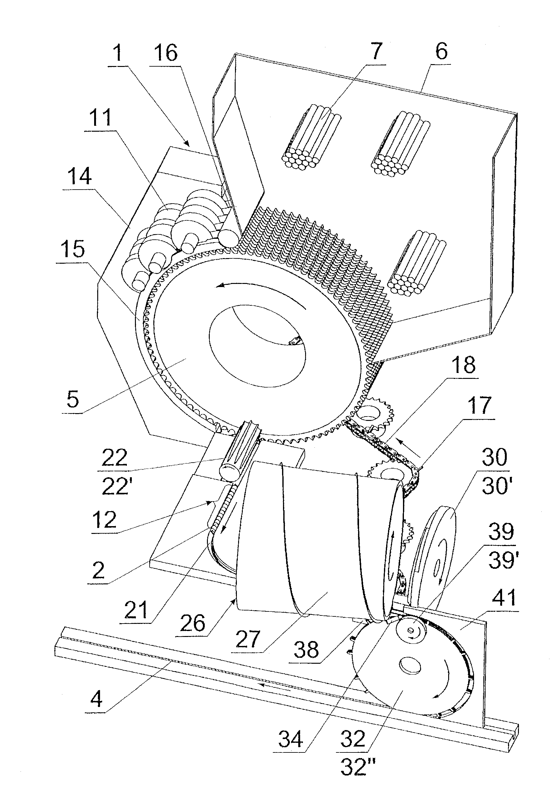
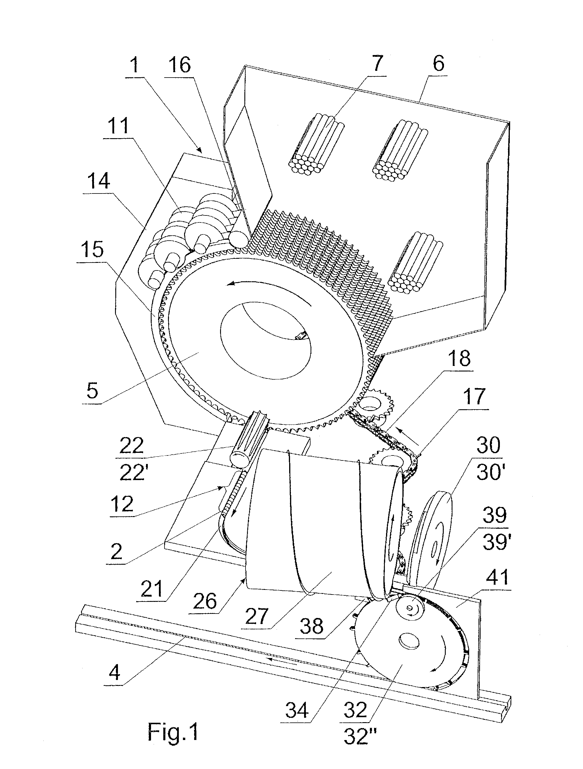
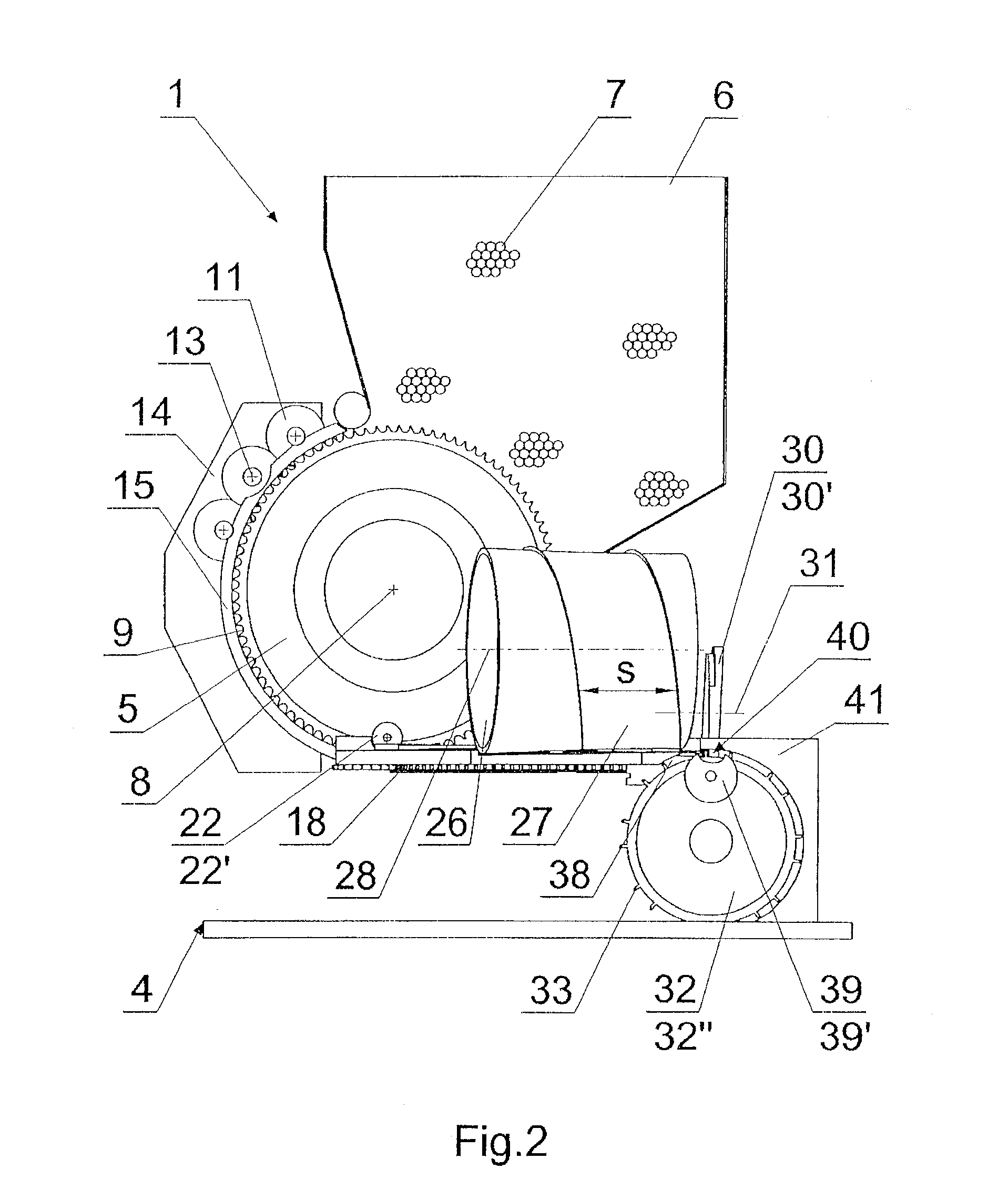
[0033]The apparatus presented in an exemplary embodiment consists of four similar modules 1, but is not confined, restricted, or limited to the application of any particular number of modules 1. The number of modules 1 is defined by the contents of segments 2 in a cigarette filter. The apparatus enables preparing and compiling groups 3 of segments 2 according to a continuous endwise manner on an exit path 4 of the apparatus in a process of producing multi-segment filters. Each module 1 is provided with a cutting drum 5 placed under a container 6 of filter rods 7 of length constituting n-multiplicity or n-multiples of length in the segment 2. The cutting drum 5 has a horizontal axis 8 (see FIG. 2) and is provided on its periphery with flutes 9 having axes 10 parallel to the axis 8 of the drum 5 (see FIG. 5). Circular knives 11 cooperate with the drum 5 and are arranged so that they cut the filter rod 7 placed in the flute 9 into the segments 2 of equal length—thus creating a set 12 o...


PUM


Abstract

A method of making segmented filters including moving substantially identical segments of one type at uniform rate to a transferring element, which places each segment separately on an exit path. Setting of the filter segments in a repeating group on the exit path is accomplished by delay in collecting segments by a transferring element in each module of the apparatus. Uniform positioning is effected using the transferring element which includes uniformly spaced drivers, and non-uniform positioning is effected using the transferring element with non-uniformly spaced drivers. The apparatus includes a guiding element positioned adjacent to a cutting drum and has a wall closing a channel for a set of segments drawn out of a flute on the drum. The filter set is led through the channel with the aid of a dog of a chain and is advanced by a worm surface of a pushing together drum. A separator positioned at the end of the channel which separates single filter segments and may be a disc cam pushing out the segment onto the transferring element between two neighbouring drivers into a chamber created by a supporting element. A stream of compressed air from nozzle directed towards the area between a shoe guide and separator helps separate and stabilize the filter segment.

Description

CROSS-REFERENCE TO RELATED APPLICATION[0001]This application claims priority under 35 U.S.C. §119 to Polish Application No. P383995, filed Dec. 10, 2007, the entire content of which is hereby incorporated by reference.BACKGROUND AND SUMMARY[0002]The subject of the invention is a method and apparatus for compiling or arranging groups of filter segments in a continuous endwise manner in a process of producing multi-segment filters used in tobacco industry for cigarettes.[0003]There is a demand in tobacco industry for multi-segment filters used in producing cigarettes. The filters consisting of at least two types of segments made of different filtrating materials. They may be soft filters filled with, e.g., fibrous material, paper, monoacetate or hard segments filled with granulate, sinter elements or hollow cylinders. A compiled set of filter segments is then divided into filters used for producing cigarettes. One method of compiling multi-segment filters is a crosswise method, the pr...

Claims


Application Information

Patent Timeline
IPC IPC(8): A24C5/32
CPCY10S493/941A24D3/0287
Inventor CIESLIKOWSKI, BARTOSZDOMINIAK, RYSZARDSIKORA, LESZEK
Owner PHILIP MORRIS USA INC
Learn More