Liquid ejection apparatus and liquid processing method

a technology of liquid ejection and liquid processing, which is applied in the direction of printing, etc., can solve the problems of air to be sucked through the ejection port, the ejection may not be provided in the correct manner, and the difference in the pressure between the common liquid chamber and the subtank

Inactive Publication Date: 2008-07-15
CANON KK
View PDF18 Cites 67 Cited by
  • Summary
  • Abstract
  • Description
  • Claims
  • Application Information

AI Technical Summary

Benefits of technology

[0030]It is an object of the present invention to provide a liquid ejection apparatus and a liquid processing method by which a circulation operation of liquid (e.g., ink) is prevented from causing air to be sucked via an ejection port or causing, on the contrary, liquid from being pushed out of an ejection port.
[0032]In the liquid ejection apparatus according to the present invention, when the pumping means is energized to stop the circulation operation for circulating the liquid between the liquid ejecting head and the subtank, the controlling means opens, simultaneously with or immediately after the stoppage of the pumping means, the air communication valve to recover the negative pressure in the subtank within a short period of time, thereby eliminating the differential pressure between the subtank and the liquid ejecting head within a short period of time.
[0033]According to the liquid ejection apparatus of the present invention, the liquid ejection apparatus comprises the controlling means for communicating, when the circulation operation is stopped, air in the subtank simultaneously with or immediately after the stoppage of the pumping means. Thus, the differential pressure between the subtank and the liquid ejecting head is eliminated within a short period of time. This can suppress air from being sucked by the ejection port, thus improving the reliability of the liquid ejection apparatus.

Problems solved by technology

This causes a tendency where the ink in a common liquid chamber is heated by a heater to have a high temperature.
However, the circulation system as described above causes the subtank to be closed while the common liquid chamber being communicated with air via the ejection port even when the circulation operation is performed in the stabilized condition, thus causing the differential pressure between the common liquid chamber and the subtank.
This has caused a case in which the negative pressure having a magnitude that exceeds an ink meniscus retention force in the ejection port causes air to be sucked via the ejection port.
When the air sucked via the ejection port is collected as bubbles in the common liquid chamber, the ejection may not be provided to a correct manner.
The ink circulation operation may have, in addition to a defect caused by the air suction as described above, a defect in which the space in the common liquid chamber is pressurized immediately after the start of the circulation operation to cause the ink to be pushed out of the ejection port.
However, the pushed-out ink is a problem in a configuration in which the pushed-out ink is collected by an independent waste ink collection tank.

Method used


Image

  • Liquid ejection apparatus and liquid processing method
  • Liquid ejection apparatus and liquid processing method
  • Liquid ejection apparatus and liquid processing method

Examples


embodiment 1

Structure of Supplying Ink Circulation System

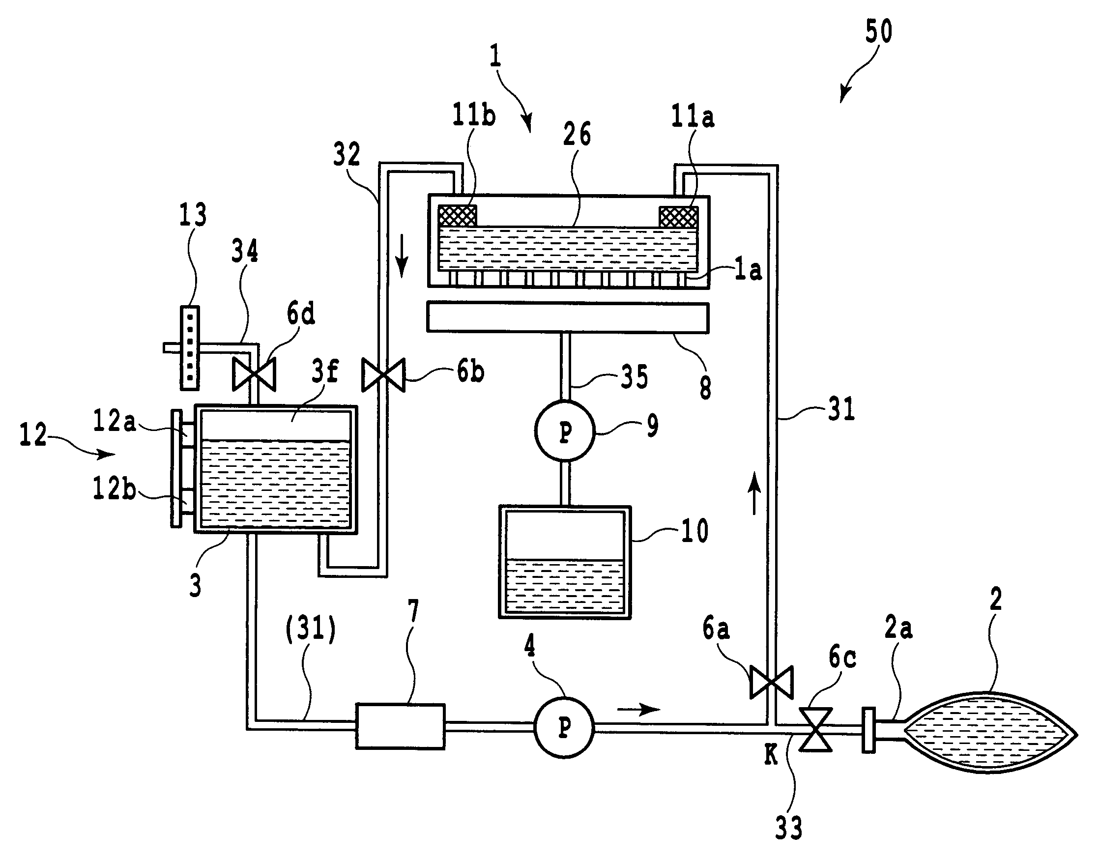
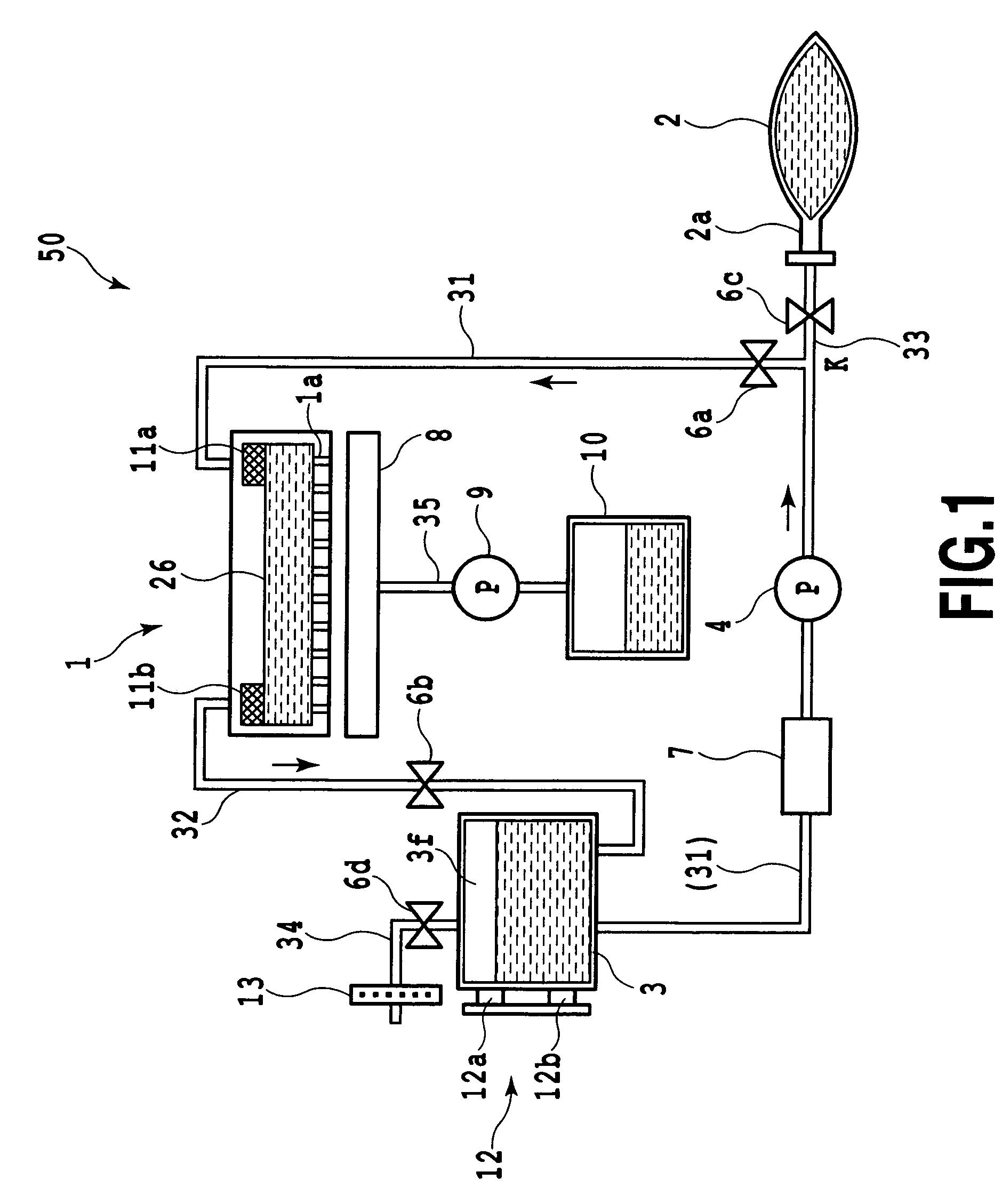
[0069]FIG. 1 is a cross-sectional view schematically showing the structure of a supplying ink circulation system according to one embodiment of the present invention.

[0070]As shown in FIG. 1, the supplying ink circulation system 50 has the full line-type ink jet head 1,the main tank 2 for storing ink supplied to the ink jet head 1, and the subtank 3 that is provided between the ink tank 2 and the ink jet head 1 and that temporally stores ink supplied from the main tank 2. The supplying ink circulation system 50 is used by being provided to an ink jet printer (not shown). The supplying ink circulation system 50 also includes, in an independent manner, the waste ink collection tank 10 for storing ink (waste ink) pushed out of the ink jet head 1.

[0071]The supplying ink circulation system 50 mainly has two passages (which will be described later). One of the passages is a circulation passage for the circulation among the ink jet head 1, the m...

embodiment 2

[0130]The circulation operation also may be provided as shown in FIG. 8. FIG. 8 is a flowchart of the circulation operation according to Embodiment 2. The circulation operation according to Embodiment 2 includes, in addition to the steps shown in the flowchart of FIG. 7, a step for controlling a switching valve immediately after the stoppage of the main pump 4 (Step S48), a step for subsequently opening the second switching valve 6b (Step S50), and a step for subsequently waiting for a predetermined time (Step S51). The same steps as those of FIG. 7 will not described further.

[0131]In Embodiment 2, a control is provided as in the first embodiment in which the circulation operation is performed for “T” seconds to subsequently stop the main pump 4 (Step S47) and then the air communication valve 6d is opened and the second switching valve 6b is closed in order to eliminate the differential pressure between the subtank 3 and the common liquid chamber 26. By closing the second switching ...


PUM


Abstract

In order to prevent, in an operation for circulating liquid, an ejection port from sucking air or the ejection port from pushing out liquid, the subtank for temporally storing ink to be supplied to the ink jet head includes the air communication passage opened or closed by the air communication valve. The ink jet head is communicated with the subtank by the first passage and the second passage to constitute one circulation passage. In order to circulate the ink in the subtank into the common liquid chamber, the main pump is energized while the air communication valve is being closed. When the circulation operation is stopped, the air communication valve is opened immediately after the stoppage of the main pump, thereby eliminating the differential pressure between the common liquid chamber and the subtank within a short period of time.

Description

BACKGROUND OF THE INVENTION[0001]1. Field of the Invention[0002]The present invention relates to a liquid ejection apparatus incorporating a supplying liquid circulation system for circulating liquid in a liquid ejecting head and the liquid processing method thereof. In particular, the present invention is suitable as an ink jet apparatus using a full line-type ink jet head in which ejection ports are arranged over the entire width of a printing medium.[0003]The term “print” described in the Specification includes, in addition to a case where significant information (e.g., characters, graphic) is formed, variety of cases such as a case where an image, marking, or pattern is formed on a printing medium or a case where the printing medium is processed (e.g., etching), regardless of the significance or non-significance and regardless of whether or not the information is elicited so as to be visually recognized by a person.[0004]The term “printing medium” includes not only a paper used ...

Claims


Application Information

Patent Timeline
Patent Type & Authority Patents(United States)
IPC IPC(8): B41J2/18B41J2/175
CPCB41J2/17503
Inventor NOMURA, HIROYASUSHIHOH, MAKOTO
Owner CANON KK
Why Eureka
Try Eureka