Multiplex-thruster systems for delivering thrusting flow

a multi-thruster and flow technology, applied in special-purpose vessels, vessel parts, vessel construction, etc., can solve the problems of difficult, repetitive, difficult, or even impossible for human divers to perform operations, and existing auvs can be expensive, cumbersome, and inflexible in functionality, so as to eliminate the difference between the pressure in and out of the vehicle

Active Publication Date: 2013-07-23
UNIV OF SOUTHERN CALIFORNIA
View PDF12 Cites 4 Cited by
  • Summary
  • Abstract
  • Description
  • Claims
  • Application Information

AI Technical Summary

Benefits of technology

[0009]In some embodiments, one or more connectors can include an adjustable valve to control the amount of fluid flown through said one or more connectors. In some embodiments, at least one connector in each of the first and second assemblies can be used not to actuate the vehicle. In some embodiments, the underwater vehicle can also include one or more pairs of vertical, starboard, or port channels. In some embodiments, the underwater vehicle can also include a modularized architecture that has one or more battery modules, embedded computers, thruster controllers, underwater communication units, water samplers and sensor modules. In some embodiments, the one or more battery modules can include at least one smart battery. In some embodiments, the one or more sensor modules comprise at least one pressure sensor to measure and maintain the vehicle at a predetermined depth from water surface. In some embodiments, the one or more sensor modules can include at least one altimeter to measure and maintain the vehicle at a predetermined distance to water bottom. In some embodiments, the one or more underwater communication units can include a radio modem in communication with a wireless Ethernet at a remote station to allow for remote access and control of the vehicle. In some embodiments, the underwater vehicle can also include an electromagnet configured to allow the vehicle to stay mutually buoyant when the electromagnet is activated to hold a predetermined weight and to float the vehicle up to water surface when the electromagnet is deactivated to drop the predetermined weight. In some embodiments, the underwater vehicle can also include a sphere shell in which the MT system resides. In some embodiments, the underwater vehicle can have a turning radius of less than about 0.1 m. In some embodiments, the sphere of the underwater vehicle can be free-flooded to eliminate pressure difference in and out the vehicle.

Problems solved by technology

These machines can perform operations that may be dangerous, repetitive, difficult, or even impossible for human divers.
Existing AUVs can be expensive, cumbersome, and inflexible in functionality.
They can be hard to acquire, difficult to deploy, inadaptable for dynamic needs, and too complex for non-experts to operate and maintain.
As a result, the use of AUVs for existing marine applications may be limited.

Method used


Image

  • Multiplex-thruster systems for delivering thrusting flow
  • Multiplex-thruster systems for delivering thrusting flow
  • Multiplex-thruster systems for delivering thrusting flow

Examples


Embodiment Construction

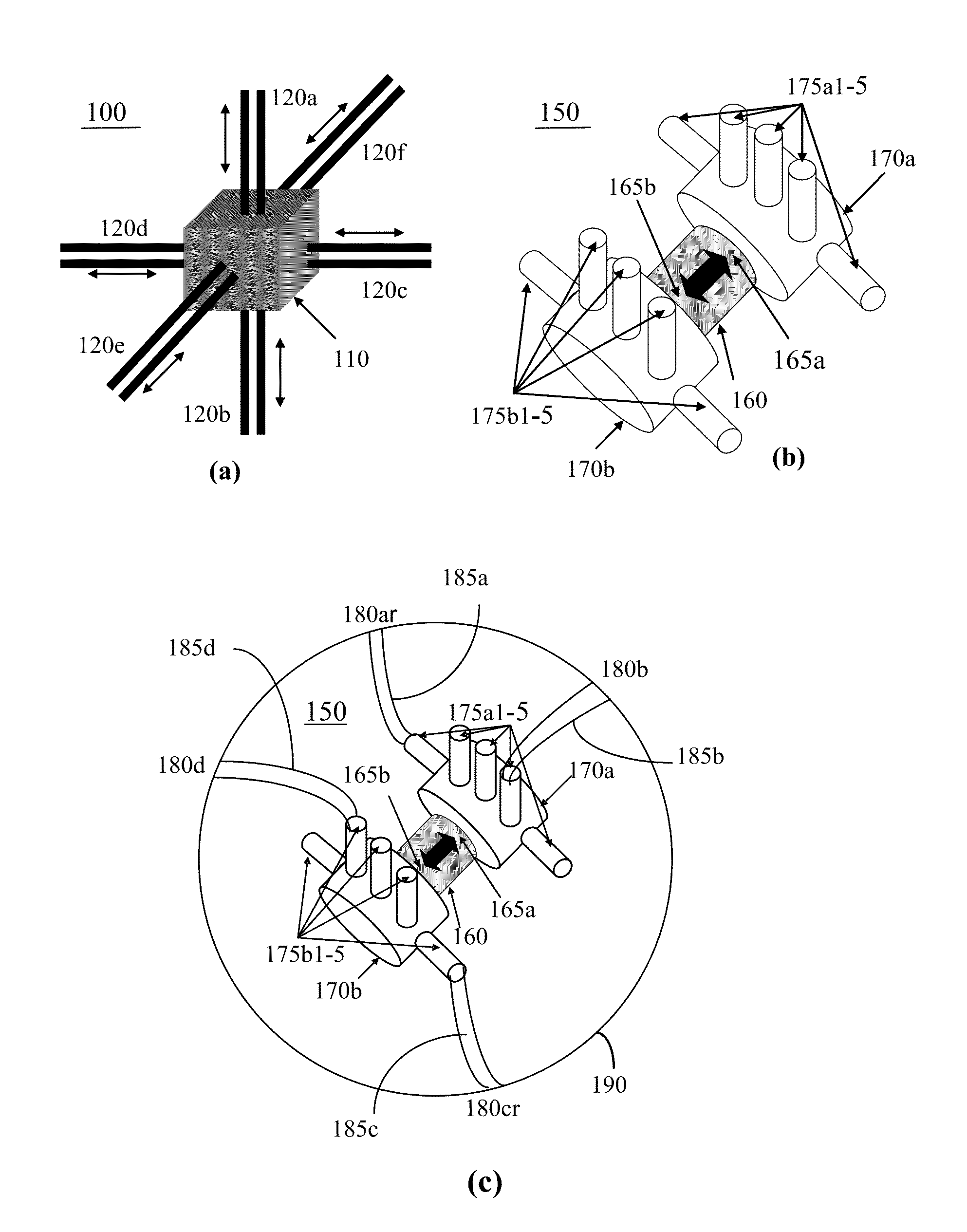
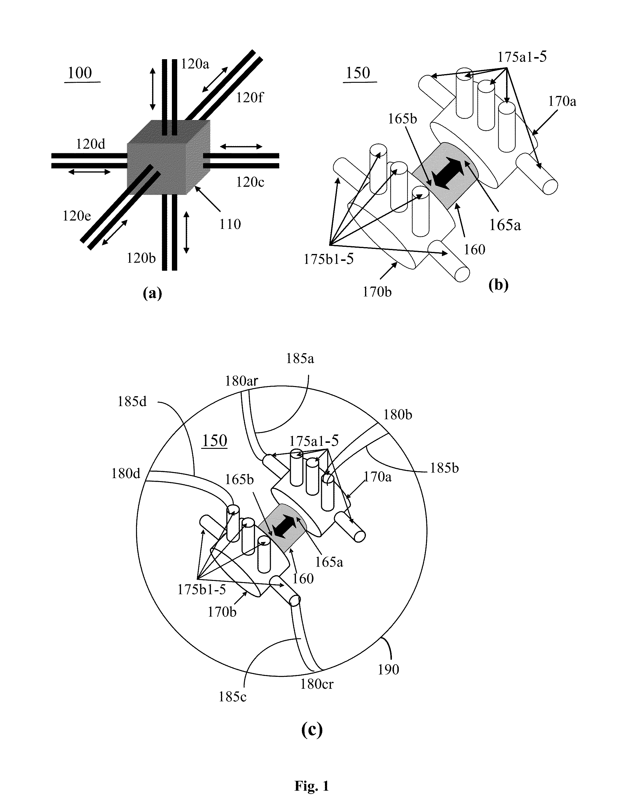
[0017]Examples of AUVs in this document use a thruster having a first end and a second end and configured to propel fluid flow in a direction from the first end to the second end and in a direction from the second end to the first end and arrange multiple first connectors or valves in fluid communication with the first end of the thruster and multiple second connectors or valves in fluid communication with the second end of the thruster. Each of the first and second connectors can be opened to allow the fluid flow and closed to block the fluid flow. The opening and closing of each connector can be individually controlled. The opening and closing of the first and second connectors and the two opposite flow directions provided by the thruster can be controlled to allow the fluid flow to enter one or more connectors and to exit one or more other connectors in various flow configurations. Hence, this combination of the first and second connectors and the thruster forms a reconfigurable ...


PUM


Abstract

Designs and techniques for fluid thrusters and vehicles that are powered by propelling fluids with fluid thrusters. Multiplex-thruster (MT) systems are disclosed that include a single thruster and a flow multiplexer with multiple channels to deliver thrusting flow in various directions.

Description

CROSS REFERENCE TO RELATED APPLICATIONS[0001]This application is a continuation application of, and claims priority to, U.S. patent application Ser. No. 12 / 392,941, entitled “MULTIPLEX-THRUSTER SYSTEMS FOR DELIVERING THRUSTING FLOW” to Wei-Min Shen, filed on Feb. 25, 2009, which claims priority under 35 U.S.C. §119(e) to U.S. Provisional Application Ser. No. 61 / 031,241, entitled “MULTIPLEX-THRUSTER SYSTEMS FOR DELIVERING THRUSTING FLOW,” and filed by Wei-Min Shen on Feb. 25, 2008. The disclosure of the above applications are incorporated herein by reference in their entirety.TECHNICAL FIELD[0002]This document relates to fluid control and apparatus and techniques for delivering thrusting flow and applications thereof.BACKGROUND[0003]Autonomous underwater vehicles (AUVs) are valuable tools for many marine applications. These machines can perform operations that may be dangerous, repetitive, difficult, or even impossible for human divers. Existing AUVs can be expensive, cumbersome, and...

Claims


Application Information

Patent Timeline
Patent Type & Authority Patents(United States)
IPC IPC(8): B63G8/08
CPCB60K3/00B63G8/001B63G8/16B63H11/107B63H25/46B63B2231/30B63B2241/14B63G8/24B63G2008/004B63H11/12B63G2008/002
Inventor SHEN, WEI-MIN
Owner UNIV OF SOUTHERN CALIFORNIA
Why Eureka
Try Eureka