Shaft seal pressure compensation system for an underwater device

a compensation system and shaft seal technology, applied in underwater equipment, special-purpose vessels, vessel construction, etc., can solve the problems of low-cost shaft seals that are not used in thruster applications, low-cost shaft seals that leak at a depth of more than 10 feet, and achieve the effect of removing any appreciable pressure differential

Inactive Publication Date: 2010-10-12
HAWKES CALVERT
View PDF5 Cites 4 Cited by
  • Summary
  • Abstract
  • Description
  • Claims
  • Application Information

AI Technical Summary

Benefits of technology

[0005]The preferred embodiments of the present invention addresses this need by compensating the internal pressure acting on the inner side of the shaft seal according to the external pressure acting on the wet side of the shaft seal. Pressure compensation is accomplished by using a variable volume space containing air that is exposed to the external pressure. As the external pressure increases when submerging the ROV, the air contained by the variable volume space is compressed according to Boyle's Law, thereby increasing the internal pressure accordingly until an equilibrium is reached between the internal pressure and external pressure, and thus eliminating any appreciable pressure differential from occurring on opposing sides of the shaft seal. Likewise, as the external pressure decreases when raising the ROV to a shallower depth, pressure equalization across the shaft seal is maintained.

Problems solved by technology

A problem with existing ROVs concerns the shaft seals inside the thrusters.
In the past, inexpensive shaft seals were generally not used for thruster applications because of the pressure differential that occurs on either side of the seal.
However, the pressure underwater increases approximately 1 PSI for every two feet of depth, so the low cost seal would leak at a depth of greater than 10 feet.
The use of more expensive seals increases the production and maintenance costs of ROVs.
Additionally, the traditional expensive seals are bulky and require ROVs using these seals to be constructed larger to accommodate the these seals, which also increases the production cost of the ROVs.
The high costs associated with the manufacture and maintenance of traditionally built ROVs with expensive shaft seals reduces the ability for the consumer market to purchase ROVs.

Method used


Image

  • Shaft seal pressure compensation system for an underwater device
  • Shaft seal pressure compensation system for an underwater device
  • Shaft seal pressure compensation system for an underwater device

Examples


Embodiment Construction

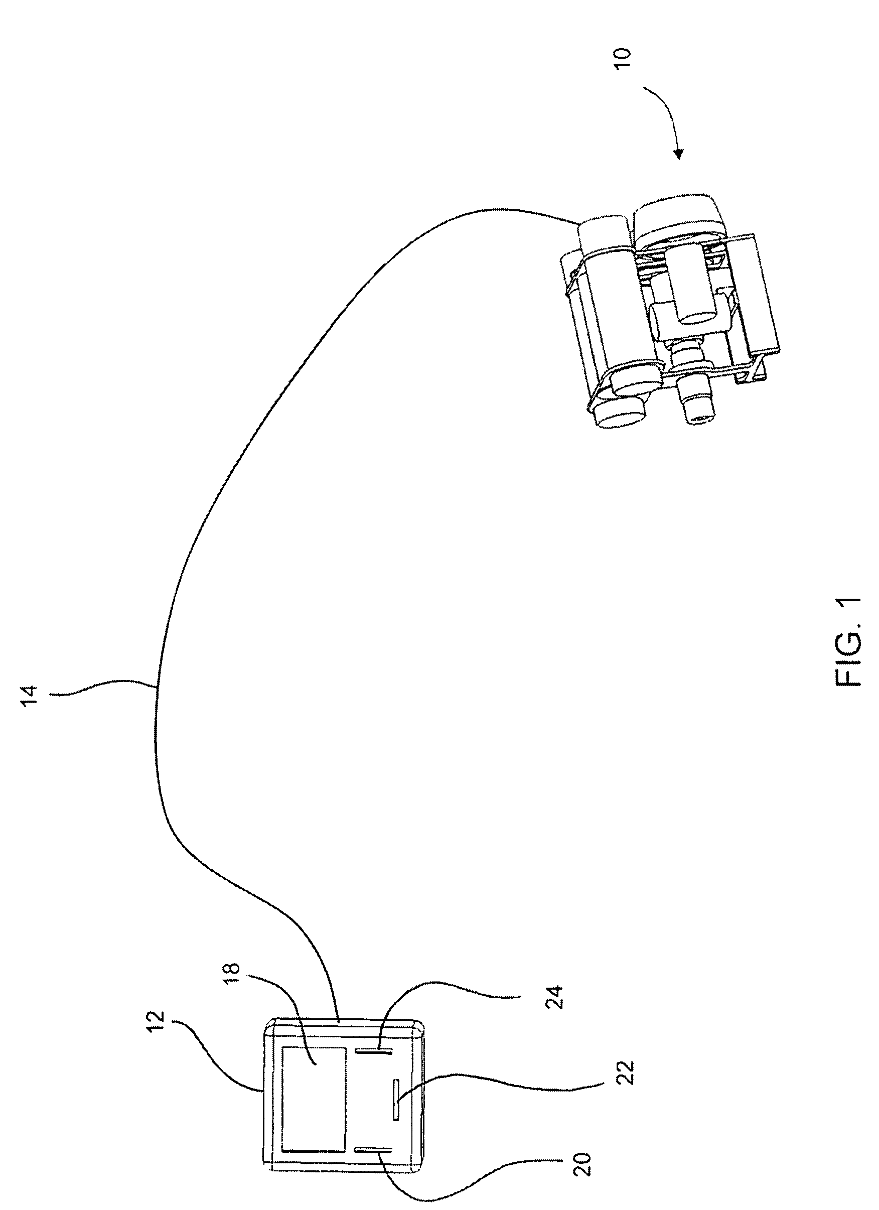
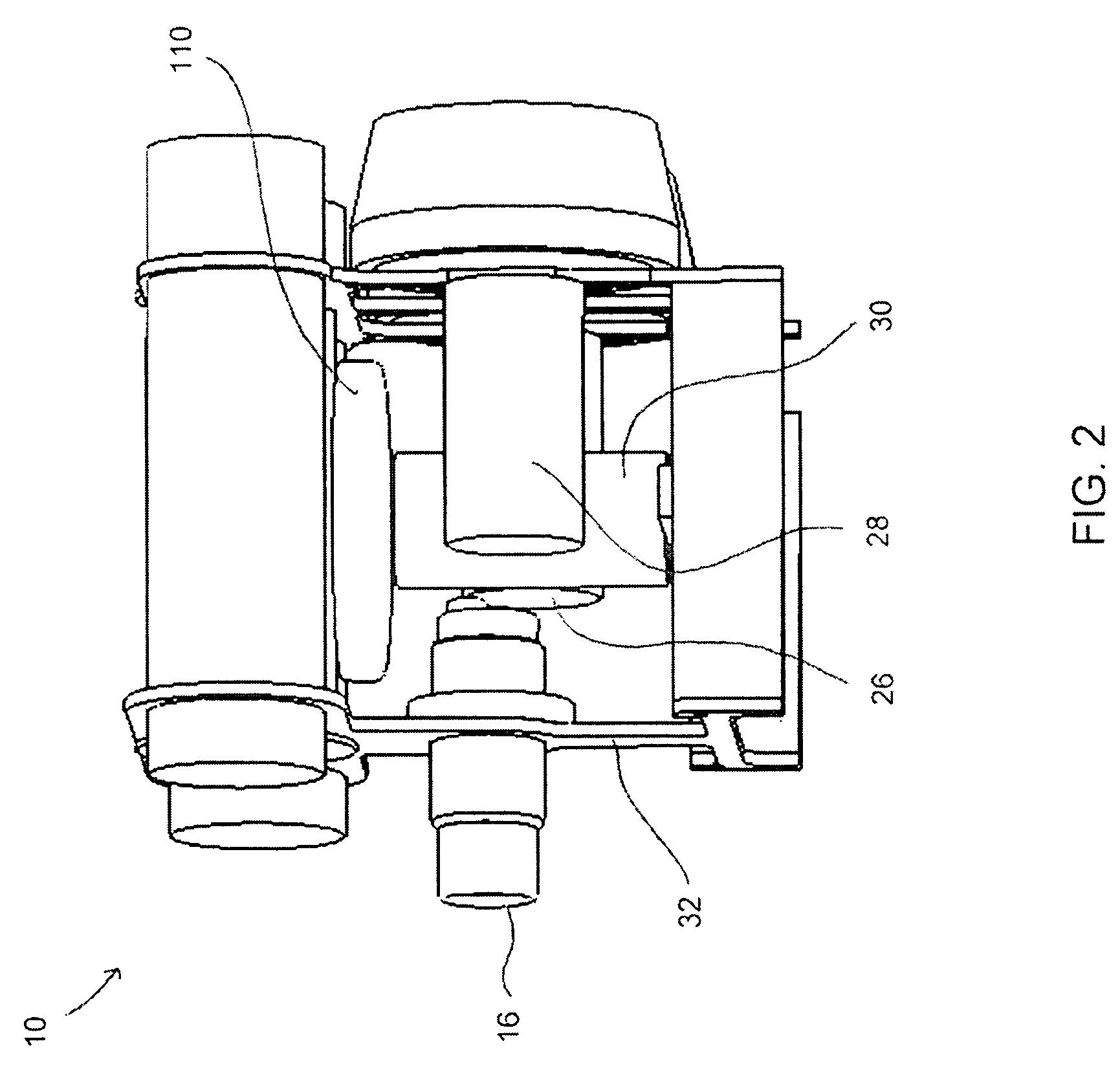
[0023]In FIG. 1, there is shown a diagrammatic perspective view of an exemplarily remote operated vehicle ROV 10 that may used in connection with the pressure compensation across a shaft seal in accordance with the principals of the present invention. The ROV 10 is connected to a base station 12 by control tether 14. The output of an ROV video camera 16 is displayed in real time on the screen of the display 18, and controls 20, 22 and 24 are used to control the movement of the ROV 10. Controls 20, 22, 24 are used to pilot the ROV 10 so as to position ROV 10 in order to display the desired information on display 18. With reference to FIG. 2, an enlarged perspective view of the exemplarily remote vehicle is shown. The ROV 10 generally includes the camera 16, horizontal thrusters 26 and 28, vertical thruster 30 all mounted to a frame 32, and a variable volume container 110.

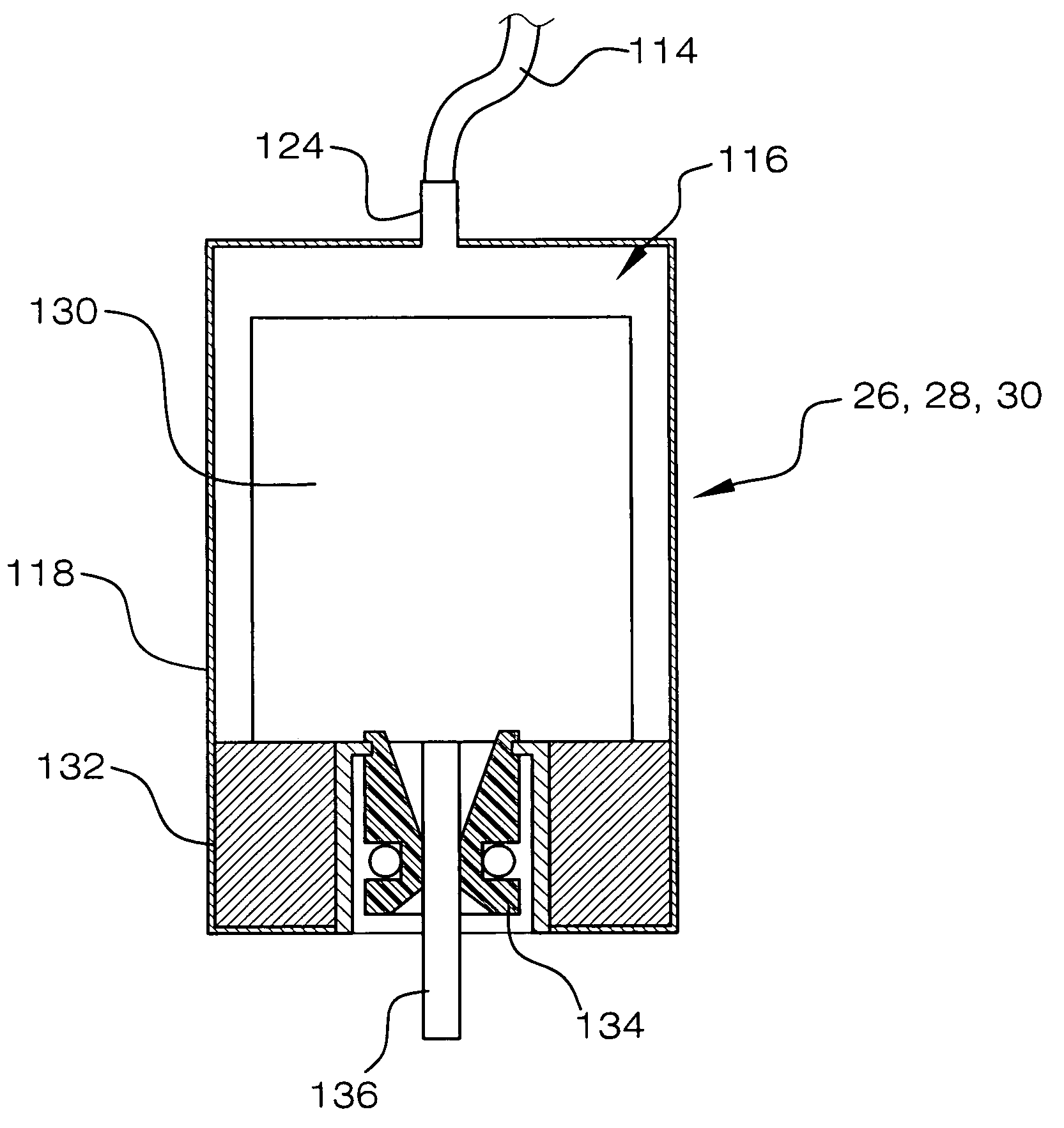
[0024]FIG. 3 illustrates the pressure compensation system 100 in accordance with the principals of the present inv...


PUM


Abstract

A shaft seal pressure compensation system for an underwater device such a remotely operated vehicle powered by motor driven thrusters where the shaft of the motor extends from a motor housing into the surrounding water and is sealed by a shaft seal by automatically supplying air to pressurize the thrusters to balance the internal pressure of the thrusters to match the ambient water pressure. The air is supplied by a variable volume container that responsive to a pressure differential between the external ambient pressure and an internal pressure within the variable volume gas container for adjusting the volume of the variable volume gas container so that the internal pressure equals the ambient pressure, and thus balancing the system.

Description

FILED OF THE INVENTION[0001]The present invention relates generally to shaft seals for underwater use, and more particularly, relating to shaft seal pressure compensation system for equalizing pressure across a thruster motor shaft seal of an underwater vehicle.BACKGROUND OF THE INVENTION[0002]Inspection class Remote Operated Vehicles (ROVs) are typically used to position a video camera underwater. The ROV usually contains electronics that are connected to a base station by a wire tether. Motor driven propellers called thrusters are used to move the ROV.[0003]A problem with existing ROVs concerns the shaft seals inside the thrusters. In the past, inexpensive shaft seals were generally not used for thruster applications because of the pressure differential that occurs on either side of the seal. These seals may tolerate a pressure differential from the wet side to the dry side of 5 PSI. However, the pressure underwater increases approximately 1 PSI for every two feet of depth, so the...

Claims


Application Information

Patent Timeline
Patent Type & Authority Patents(United States)
IPC IPC(8): B63H23/36B63G8/00
CPCB63H23/321
Inventor HAWKES, CALVERT
Owner HAWKES CALVERT
Why Eureka
Try Eureka