
Main shaft automatic lubricating device capable of avoiding increase of rotating friction

An automatic lubrication and rotational friction technology, applied in the direction of engine lubrication, engine components, mechanical equipment, etc., can solve the problems of automatic identification and lubrication, reduce work efficiency, increase energy waste, etc., to avoid energy waste and save work Time, the effect of prolonging the working life

Inactive Publication Date: 2021-12-10
张洪刚
View PDF0 Cites 1 Cited by
  • Summary
  • Abstract
  • Description
  • Claims
  • Application Information

AI Technical Summary

Problems solved by technology

[0005] Aiming at the deficiencies of the prior art, the present invention provides an automatic spindle lubrication device that avoids the increase of rotational friction, which can automatically lubricate the spindle according to its working state, saves working time, improves work efficiency, and can Lubricate it when the speed is abnormal, which avoids the waste of energy and prolongs the working life of the main shaft. It solves the problem that the lubrication of the main shaft bearing needs to manually add lubricating oil on its surface to improve the normal use of the main shaft, which cannot be automatically identified and Lubrication reduces work efficiency and increases energy waste

Method used


Image

  • Main shaft automatic lubricating device capable of avoiding increase of rotating friction
  • Main shaft automatic lubricating device capable of avoiding increase of rotating friction
  • Main shaft automatic lubricating device capable of avoiding increase of rotating friction

Examples


Embodiment Construction

[0024] The following will clearly and completely describe the technical solutions in the embodiments of the present invention with reference to the accompanying drawings in the embodiments of the present invention. Obviously, the described embodiments are only some, not all, embodiments of the present invention. Based on the embodiments of the present invention, all other embodiments obtained by persons of ordinary skill in the art without making creative efforts belong to the protection scope of the present invention.

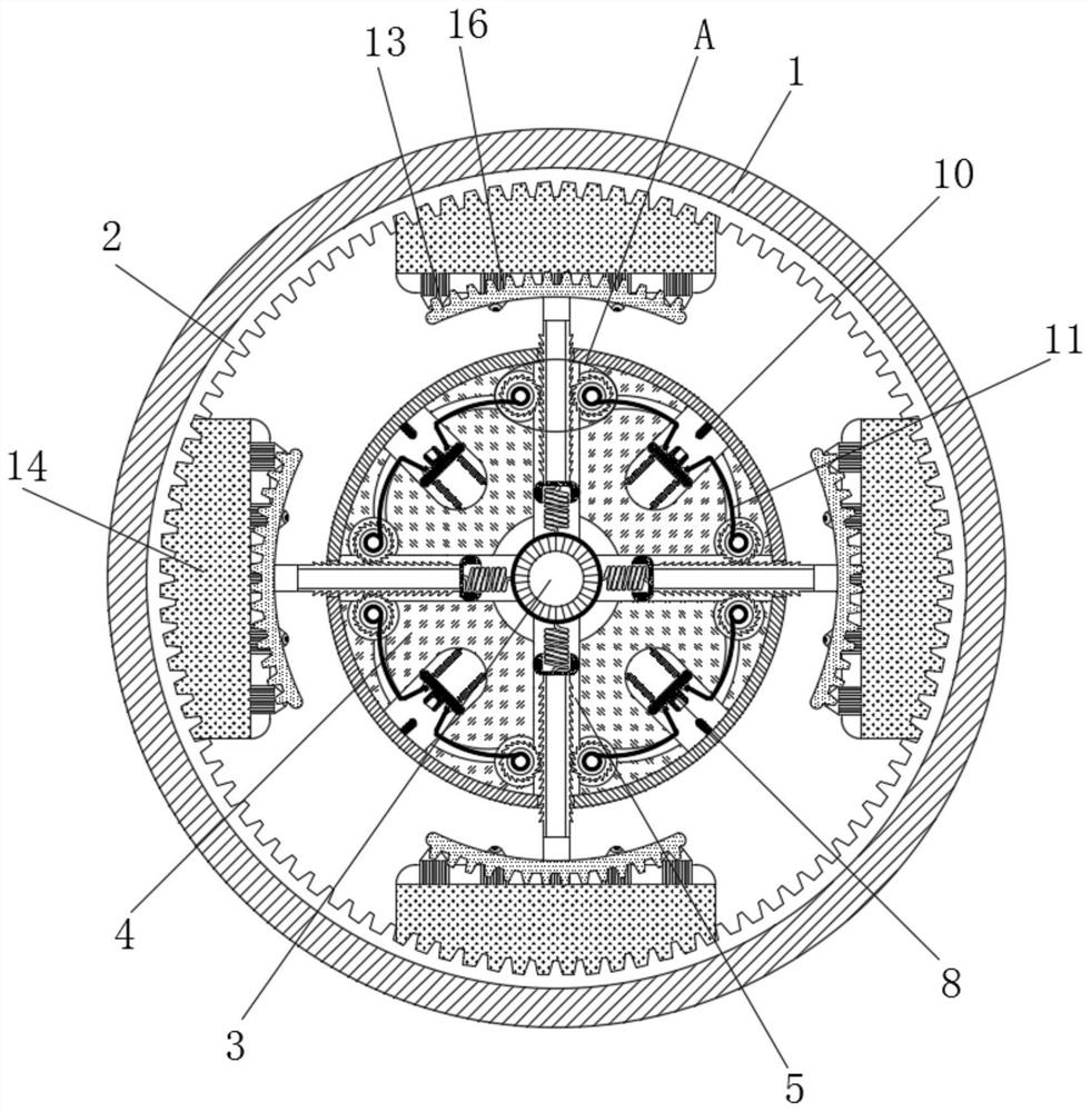
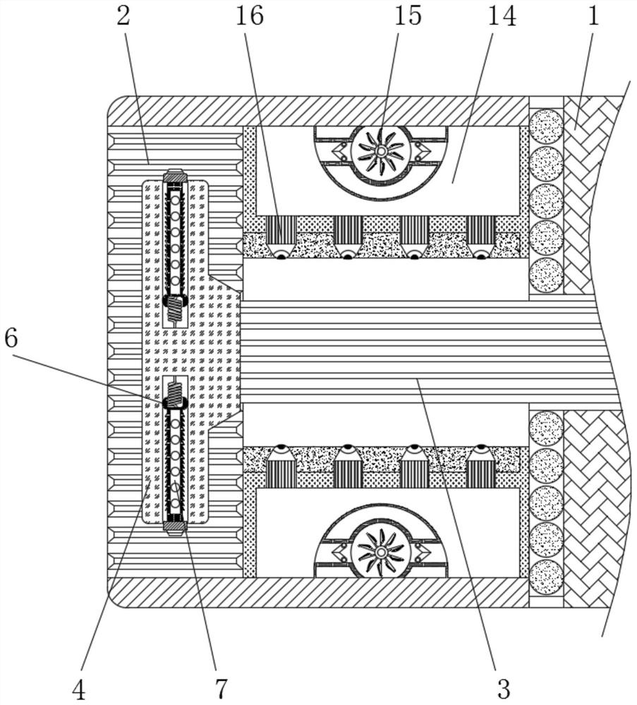
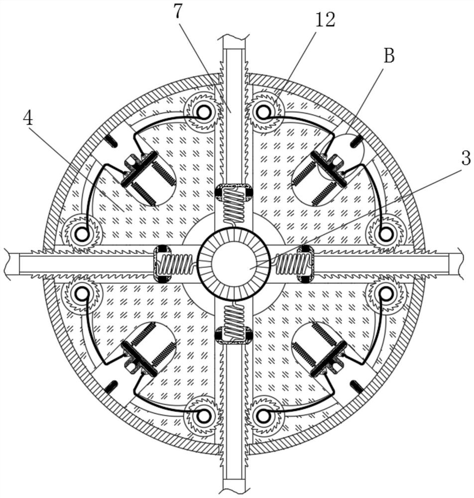
[0025] see Figure 1-5 , an automatic spindle lubricating device for avoiding the increase of rotational friction, comprising a frame 1, the side wall inside the frame 1 is fixedly connected with an inner rack 2, and the center inside the frame 1 is rotatably connected with a rotating shaft 3, and the rotating shaft 3 is far away from the turntable 4 One end of the shaft is connected with the main shaft gear, the surface of the shaft 3 is provided with a groov...


PUM


Abstract

The invention relates to the technical field of multi-shaft machining centers, and discloses a main shaft automatic lubricating device capable of avoiding increase of rotating friction. The main shaft automatic lubricating device comprises a machine frame, an inner rack is fixedly connected to the side wall in the machine frame, a rotating shaft is rotatably connected to the center in the machine frame, and a rotating disc is fixedly connected to the end part of the rotating shaft. A sliding groove is formed in the rotating disc, a sliding block is slidably connected into the sliding groove, a ratchet bar is fixedly connected to the end of the sliding block, a sliding plate is slidably connected into the rotating disc, a metal strip is fixedly connected into the sliding plate, and a metal feeler lever is fixedly connected to the side face, close to the sliding plate, of the rotating disc. When the rotating speed of a main shaft is lower than the normal rotating speed range, the metal feeler lever makes contact with the metal strip under the action of centrifugal force, the interior of the main shaft starts to be lubricated, and therefore the effects that the main shaft can be automatically lubricated according to the working state of the main shaft, the working time is saved, and the working efficiency is improved are achieved.

Description

technical field [0001] The invention relates to the technical field of multi-axis machining centers, in particular to an automatic lubrication device for a main shaft that avoids increased rotational friction. Background technique [0002] Inside the machining center, the internal components will be lubricated by the flow of lubricating oil, but the surface of the main shaft exposed to the air will cause the lubricating oil to dry up quickly due to the oxidation of the air, resulting in poor lubrication. Now The lubrication of the main shaft bearing needs to manually add lubricating oil on its surface to improve the normal use of the main shaft, but it cannot be automatically identified and lubricated, which reduces work efficiency and increases energy waste. [0003] In order to solve the above problems, the inventor provides an automatic spindle lubrication device that avoids the increase of rotational friction. Through the mutual meshing of the positioning gear and the in...

Claims


Application Information

Patent Timeline
IPC IPC(8): F16N7/38F16N7/36
CPCF16N7/38F16N7/363
Inventor 张洪刚
Owner 张洪刚
Learn More