Permanent magnet reluctance motor with double-stator non-uniform tooth structure

A reluctance motor, non-uniform technology, applied in the direction of magnetic circuit shape/style/structure, magnetic circuit, electromechanical device, etc., can solve the problems of low stator space utilization rate, long winding end, etc., to improve motor efficiency and power density , The rotor wind resistance is small, the effect of increasing the average torque

Active Publication Date: 2021-12-10
HUAZHONG UNIV OF SCI & TECH
View PDF4 Cites 0 Cited by
  • Summary
  • Abstract
  • Description
  • Claims
  • Application Information

AI Technical Summary

Problems solved by technology

[0005] In view of the above defects or improvement needs of the prior art, the present invention provides a permanent magnet reluctance motor with a double-stator non-uniform tooth structure. The purpose is to effectively improve the efficiency and power density of the motor while avoiding long winding ends, Problems such as low stator space utilization

Method used


Image

  • Permanent magnet reluctance motor with double-stator non-uniform tooth structure
  • Permanent magnet reluctance motor with double-stator non-uniform tooth structure
  • Permanent magnet reluctance motor with double-stator non-uniform tooth structure

Examples


Embodiment Construction

[0027] In order to make the object, technical solution and advantages of the present invention clearer, the present invention will be further described in detail below in conjunction with the accompanying drawings and embodiments. It should be understood that the specific embodiments described here are only used to explain the present invention, not to limit the present invention. In addition, the technical features involved in the various embodiments of the present invention described below can be combined with each other as long as they do not constitute a conflict with each other.

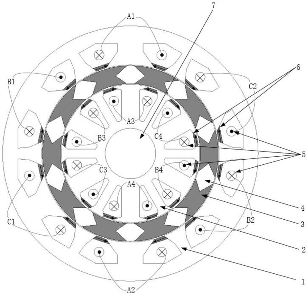
[0028] The invention provides a permanent magnet reluctance motor with a double-stator non-uniform tooth structure, including:

[0029] shaft;

[0030] The inner stator is arranged on the outer side of the rotating shaft, and is provided with a plurality of alternately evenly distributed first teeth and second teeth, the size of the first teeth is larger than that of the second teeth; each firs...


PUM


Abstract

The invention discloses a permanent magnet reluctance motor with a double-stator non-uniform tooth structure, and belongs to the field of motors. The permanent magnet reluctance motor comprises a rotating shaft, an inner stator, a rotor, an outer stator and a plurality of permanent magnets. The inner stator is provided with a plurality of first teeth and second teeth which are alternately and uniformly distributed; coils are wound on the first teeth to generate a first magnetic field when electrified; the outer stator is provided with a plurality of third teeth and fourth teeth which are alternately and uniformly distributed; coils are wound on the third teeth to generate a third magnetic field when electrified; the third magnetic field is opposite to the first magnetic field; in the inner stator, a permanent magnet is used for generating a second magnetic field, and the direction of the second magnetic field is the same as that of the first magnetic field to establish an inner air-gap magnetic field; and in the outer stator, a permanent magnet is used for generating a fourth magnetic field, and the fourth magnetic field and the third magnetic field are identical in direction to establish an outer air-gap magnetic field. The internal space of the motor is utilized to generate torque, the coils are wound on the large teeth of the stator, the ends of the coils are very short, all phases are not overlapped, and the winding utilization rate is high.

Description

technical field [0001] The invention belongs to the field of motors, and more specifically relates to a permanent magnet reluctance motor with a double-stator non-uniform tooth structure. Background technique [0002] The stator and rotor of the switched reluctance motor have a double-salient pole structure, and the rotor has no windings. It has the advantages of simple structure, low cost, high reliability, strong fault tolerance, and wide constant power speed regulation range. However, the power density of switched reluctance motors is not as good as that of conventional permanent magnet motors. In order to improve the performance of the motor and obtain higher torque performance and power density, people have proposed a segmented rotor structure or added permanent magnets to assist the formation of a hybrid excitation reluctance motor. [0003] At present, the whole-pitch winding block rotor switched reluctance motor researched in the world adopts the stator winding with...

Claims


Application Information

Patent Timeline
IPC IPC(8): H02K16/04H02K1/14H02K1/17H02K1/22H02K1/30
CPCH02K16/04H02K1/146H02K1/17H02K1/22H02K1/30H02K2213/03
Inventor 孙剑波杨洋魏黄丽甘醇曲荣海
Owner HUAZHONG UNIV OF SCI & TECH
Why Eureka
Try Eureka