Iron core punching sheet for outer rotor permanent magnet synchronous motor

A permanent magnet synchronous motor and rotor punching technology, applied in the direction of magnetic circuits, electromechanical devices, electrical components, etc., can solve the problems of low torque density and power density, low cogging torque, low reluctance torque, etc. Achieve the effect of high torque density and power density, large reluctance torque

Pending Publication Date: 2022-06-28
玉柴芯蓝新能源动力科技有限公司
View PDF3 Cites 0 Cited by
  • Summary
  • Abstract
  • Description
  • Claims
  • Application Information

AI Technical Summary

Problems solved by technology

[0005] However, in the structure of the outer rotor permanent magnet synchronous motor of the range extender, it is necessary to have low cogging torque and lower torque ripple. The conventional inner rotor motor and the conventional outer rotor motor in the above-mentioned prior art, the reluctance torque Low, low torque density and low power density, it is difficult to meet the working requirements of high torque density and high power density

Method used


Image

  • Iron core punching sheet for outer rotor permanent magnet synchronous motor
  • Iron core punching sheet for outer rotor permanent magnet synchronous motor
  • Iron core punching sheet for outer rotor permanent magnet synchronous motor

Examples


Embodiment 1

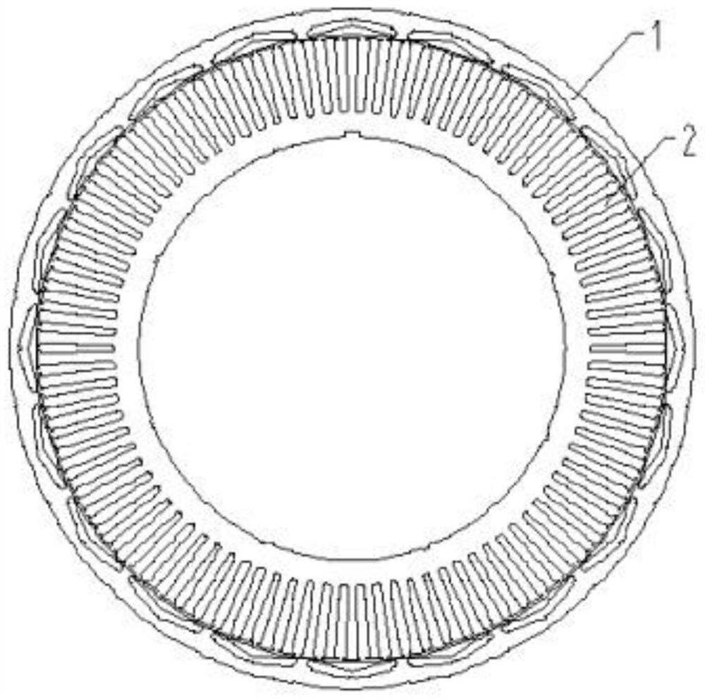
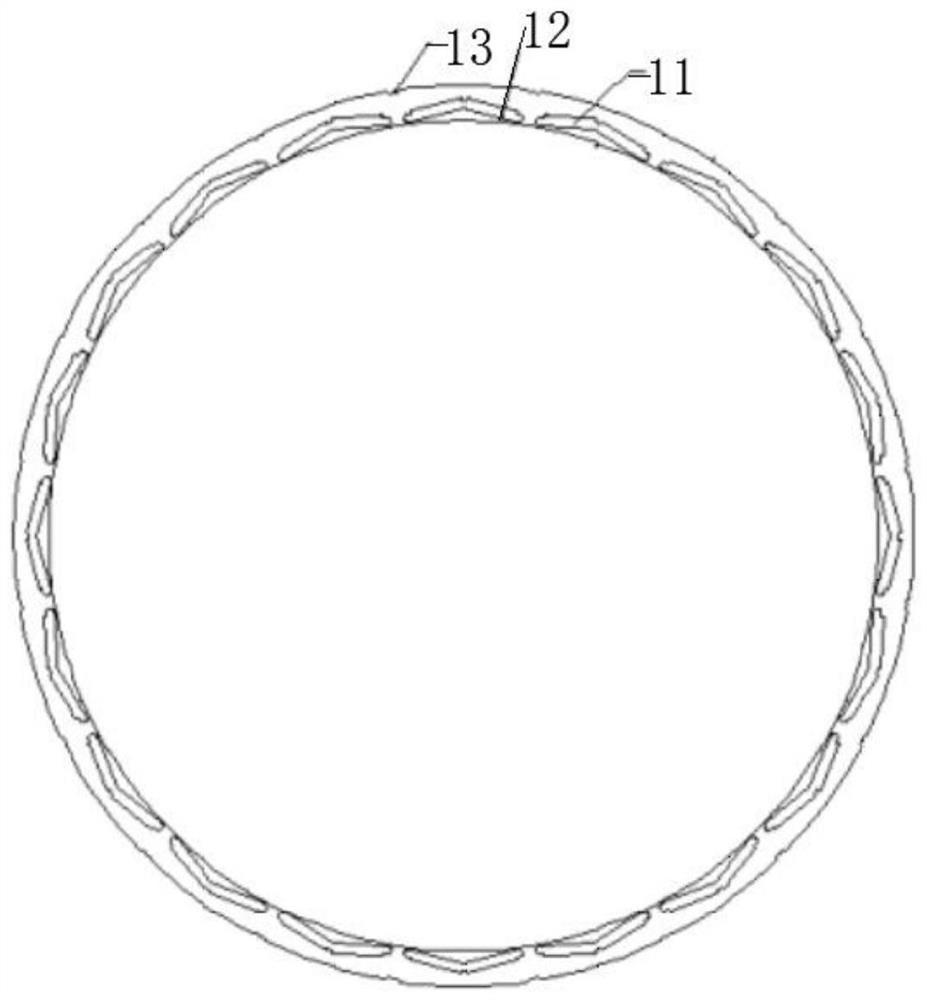
[0037] like Figure 1 to Figure 3 As shown, an iron core punch for an outer rotor permanent magnet synchronous motor includes a stator punch 2 and a rotor punch 1 that cooperate with each other, and both the stator punch 2 and the rotor punch 1 are annular, The outer diameter of the rotor punching sheet 1 is larger than that of the stator punching sheet 2, and the body of the rotor punching sheet 1 is uniformly opened with V-shaped grooves 11 along the circumferential direction;

[0038] like Image 6 As shown, the opening of the V-shaped groove 11 is along the inner diameter direction, and is used to place the permanent magnet 3;

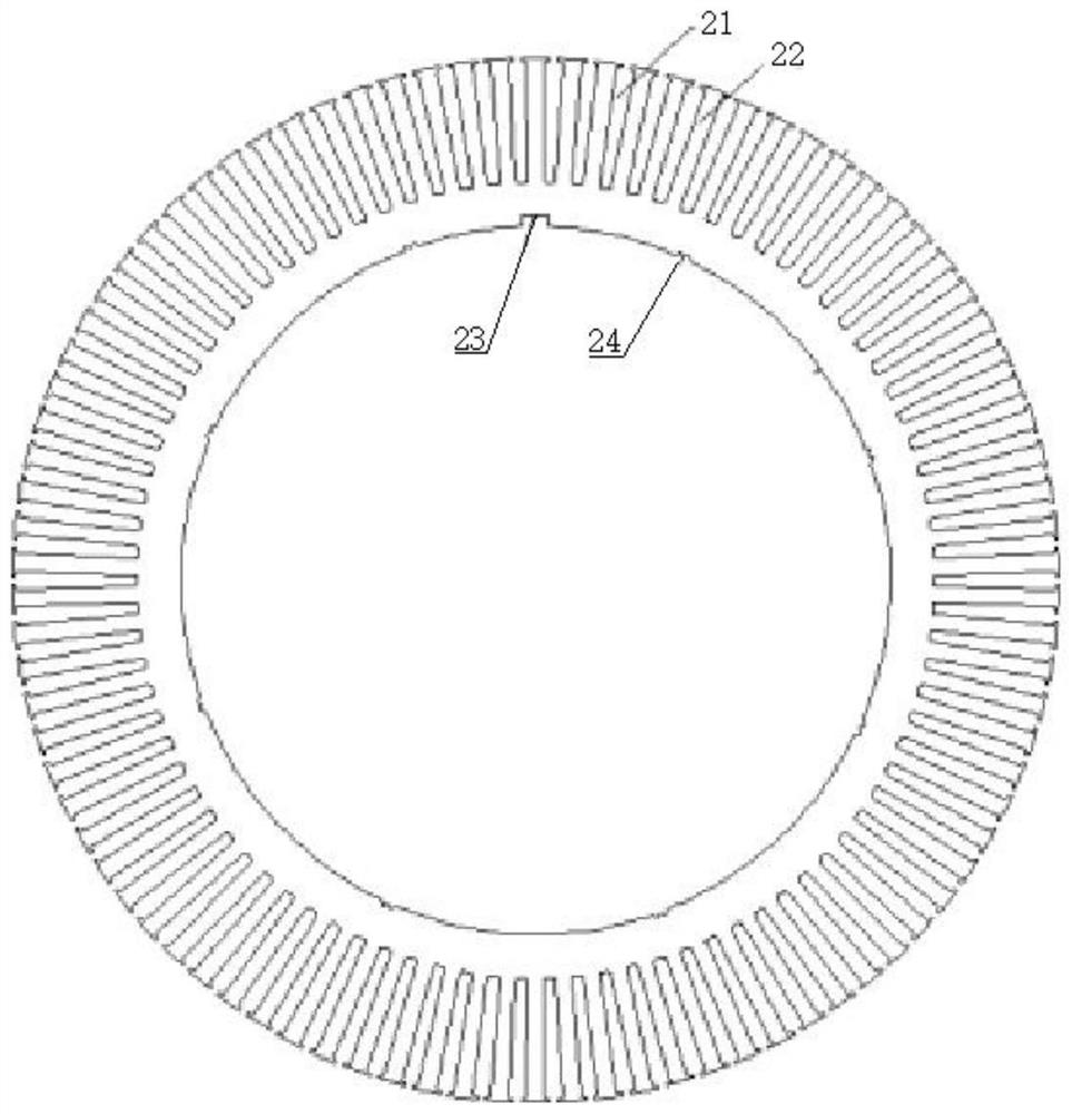
[0039] like image 3 As shown, the stator punching piece 2 is evenly provided with radial opening slots 21 along the outer diameter and circumferential direction; the calculated pole arc coefficient of the rotor punching piece 1 is 0.65-0.7;

[0040] like Figure 4 As shown, auxiliary grooves 12 are distributed on the inner diameter and circumf...

Embodiment 2

[0043] This embodiment is an iron core punching sheet for an outer rotor permanent magnet synchronous motor. The main components are composed of a stator iron core and a rotor iron core. They are both punched and punched from silicon steel sheets and then laminated, such as figure 1 and Image 6 As shown, it is used for a permanent magnet synchronous motor in which the permanent magnet 3 is placed inside the rotor core of the motor;

[0044] like Figure 1 to Figure 3 As shown, including the stator punch 2 and the rotor punch 1 that cooperate with each other, the two parts are used together in pairs and cannot be used alone;

[0045] like figure 2 and image 3 As shown in the figure, both the stator punch 2 and the rotor punch 1 are annular, the outer diameter of the rotor punch 1 is larger than that of the stator punch 2, and the body of the rotor punch 1 is uniform in the circumferential direction A V-shaped groove 11 is opened, the opening of the V-shaped groove 11 is ...

Embodiment 3

[0064] The difference between this embodiment and the above-mentioned Embodiment 2 is that the calculated pole arc coefficient of the rotor punch 1 is 0.7, the depth H from the bottom of the auxiliary groove 12 to the inner diameter circumference of the rotor punch 1 is 0.4 mm, and α =5.2°, the outer diameter of the rotor punch 1 is 480 mm, the annular width of the rotor punch 1 is 20 mm, and the gap between the inner diameter of the rotor punch 1 and the outer diameter of the stator punch 2 is 1.5 mm.


PUM

PropertyMeasurementUnit
Depthaaaaaaaaaa
Diameter sizeaaaaaaaaaa

Abstract

The invention relates to the field of range extender outer rotor generator stator and rotor iron core punching sheet magnetic circuits, in particular to an iron core punching sheet for an outer rotor permanent magnet synchronous motor, which comprises a stator punching sheet and a rotor punching sheet matched with each other, the stator punching sheet and the rotor punching sheet are ring-shaped, the outer diameter of the rotor punching sheet is larger than that of the stator punching sheet, and the rotor punching sheet is arranged on the stator punching sheet. V-shaped grooves are uniformly formed in the body of the rotor punching sheet along the circumferential direction, and the openings of the V-shaped grooves are along the inner diameter direction; radial open slots are uniformly formed in the stator punching sheet in the circumferential direction of the outer diameter; the calculated pole-arc coefficient of the rotor punching sheet is 0.65-0.7, auxiliary grooves are distributed on the circumference of the inner diameter of the rotor punching sheet, and the auxiliary grooves are symmetrically arranged on two sides of the axis of the V-shaped groove in pairs. The auxiliary grooves are designed on the two sides of the axis of the V-shaped groove, the reasonable calculation pole-arc coefficient is set, and compared with a synchronous motor with the permanent magnet body attached to the surface of the rotor iron core, the motor has larger reluctance torque and higher torque density and power density.

Description

technical field [0001] The invention relates to the field of magnetic circuits of stators and rotor iron core punching pieces of a range extender outer rotor generator, in particular to an iron core punching piece for an outer rotor permanent magnet synchronous motor. Background technique [0002] In the prior art, there are many external rotor generator structures for range extenders. For example, Chinese patent CN209283014U discloses a permanent magnet generator for an automobile range extender, which includes a motor casing, an inner stator with windings, an outer rotor and a rotating shaft, with The inner stator with winding is arranged in the inner cavity of the motor casing, the inner end of the inner stator with winding is fixedly connected with the inner end of the electric motor casing, the outer rotor is arranged in the inner cavity of the motor casing, the outer rotor is sleeved outside the inner stator with winding, the outer The rotor is connected with the rotat...

Claims


Application Information

Patent Timeline
IPC IPC(8): H02K1/279H02K1/16
CPCH02K1/2786H02K1/16H02K2213/03
Inventor 曾强毛正松陈涛张松欧阳石坤司政勇奉智卿李邓勰
Owner 玉柴芯蓝新能源动力科技有限公司
Why Eureka
Try Eureka