Vernier permanent magnet motor with transversely staggered stator modulation teeth

A lateral dislocation, permanent magnet motor technology, applied in the direction of motor, magnetic circuit, electric components, etc., can solve the problems of low space utilization, high power density, high torque, etc., to reduce copper consumption and high torque density , the effect of improving torque density and power density

Active Publication Date: 2022-01-14
HARBIN INST OF TECH
View PDF6 Cites 0 Cited by
  • Summary
  • Abstract
  • Description
  • Claims
  • Application Information

AI Technical Summary

Problems solved by technology

Transverse flux motors are suitable for direct drive systems because of the decoupling of electric and magnetic loads in space, low speed, high torque, and high power density. However, the existing transverse flux motors have low space utilization The problem

Method used


Image

  • Vernier permanent magnet motor with transversely staggered stator modulation teeth
  • Vernier permanent magnet motor with transversely staggered stator modulation teeth
  • Vernier permanent magnet motor with transversely staggered stator modulation teeth

Examples


specific Embodiment approach 1

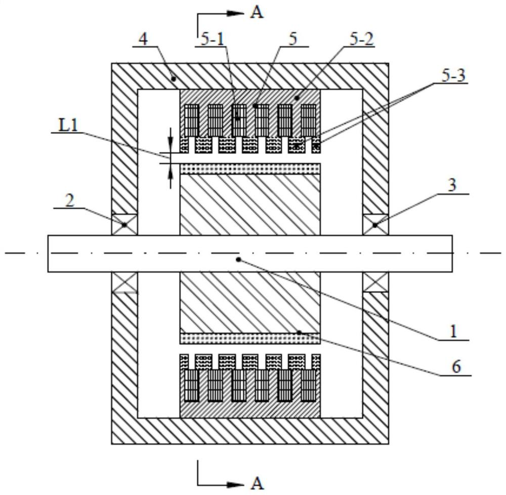
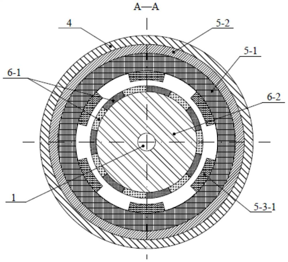
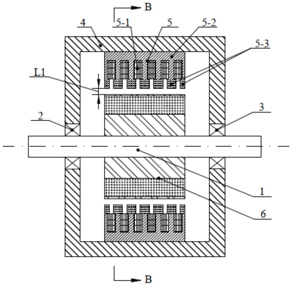
[0043] Specific implementation mode one: the following combination figure 1 , figure 2 , Figure 13 and Figure 14 Describe this embodiment mode, a kind of vernier permanent magnet motor of stator modulating tooth lateral dislocation described in this embodiment mode, it comprises casing 4, stator 5, permanent magnet rotor 6, permanent magnet rotor output shaft 1; Stator 5 is fixed on casing On the inner circle surface of 4, the permanent magnet rotor 6 is fixed on the output shaft 1 of the permanent magnet rotor, and is rotationally connected with the side end cover of the casing 4 through bearings 2 and 3.

[0044] The slots of the stator 5 are arranged in the form of semi-closed slots along the axial direction with equal tooth widths, the tooth widths of the two ends are 1 / 2 of the middle tooth width, and the slots of the semi-closed slots of the stator core 5-2 face the permanent magnet rotor 6. The ring winding 5-1 is embedded in the semi-closed slot; the ring winding...

specific Embodiment approach 2

[0087] Specific implementation mode two: the following combination image 3 and Figure 4 Describe this embodiment. The difference between this embodiment and Embodiment 1 is that n×2p PM A permanent magnet 6-1 is embedded in the permanent magnet rotor core 6-2, the cross section of the permanent magnet 6-1 is rectangular, n×2p PM The permanent magnets 6-1 are radially distributed inside the permanent magnet rotor core 6-2 with the permanent magnet rotor output shaft 1 as the center, and the magnetization direction of the permanent magnets 6-1 is tangential parallel magnetization.

[0088] In this embodiment, the permanent magnet rotor belongs to the magnetic accumulation structure. Under the parallel action of the adjacent permanent magnets of the permanent magnet rotor, it has a prominent effect on increasing the air gap magnetic density, thereby increasing the no-load back electromotive force and electromagnetic torque of the motor.

specific Embodiment approach 3

[0089] Specific implementation mode three: the following combination Figure 5 and Figure 6 Describe this embodiment. The difference between this embodiment and Embodiment 1 is that n×2p PM A permanent magnet 6-1 is embedded in the permanent magnet rotor core 6-2, the cross section of the permanent magnet 6-1 is rectangular, the magnetization direction of the permanent magnet 6-1 is parallel magnetization, and the magnetic force line passing through the midpoint is a Towards.


PUM


Abstract

The invention discloses a vernier permanent magnet motor with transversely staggered stator modulation teeth, which belongs to the field of motors, and aims to solve the problem of low space utilization rate of an existing transverse flux motor. The motor comprises a stator and a permanent magnet rotor. The stator comprises an annular winding, a stator core and stator modulation teeth, the annular winding is an m-phase stator winding, and when m-phase alternating current passes through the annular winding, an axial armature magnetic field with ps pole pairs can be generated; the stator modulation tooth and the permanent magnet rotor adopt a unit motor rotor form along the circumferential direction of the motor, the number of unit motors is n, the stator modulation tooth comprises n*(pm+1)*pPM magnetic conductive blocks, pm is the number of stator slots, (pm+1) circles of the n*(pm+1)*pPM magnetic conductive blocks on the stator modulation tooth are arranged at equal intervals along the axial direction, n*pPM magnetic conductive blocks are arranged in each circle, and the (pm+1) circles of magnetic conductive blocks are sequentially staggered by 2pi / npm along the circumferential direction, at the moment, the two outermost rings are axially aligned; meanwhile, the condition ps=|ipPM+ / -kpm| is met.

Description

technical field [0001] The invention relates to a permanent magnet motor body structure, in particular to a magnetic field modulation vernier permanent magnet motor. Background technique [0002] With the global energy crisis and environmental degradation becoming more and more serious, the fields of wind power generation, electric vehicles and ship drives have attracted extensive attention from scholars at home and abroad, and low-speed high-torque direct-drive motors used in these fields have become the current research hotspots. [0003] At present, the common low-speed and high-torque realization methods include: 1) Convert high speed to low speed through traditional mechanical gears, and then increase the torque of the device accordingly, but the mechanical gear system has large volume, large noise, mechanical wear and low reliability 2) The use of magnetic gears to increase the torque performance of the device is the same as that of mechanical gears, except that the t...

Claims


Application Information

Patent Timeline
IPC IPC(8): H02K1/16H02K1/12H02K1/278
CPCH02K1/16H02K1/12H02K1/278H02K2213/03Y02T10/64
Inventor 郑萍王于涛白金刚刘国鹏梁晓宇高家林
Owner HARBIN INST OF TECH
Why Eureka
Try Eureka