Minimally invasive electrical stimulation system

A technology of electrical stimulation and stimulators, applied in the field of minimally invasive electrical stimulation systems, can solve the problems of limited battery life, inability to release current, and large implant damage, and achieve precise stimulation doses, solve the problems of battery, and control stimulation doses Effect

Pending Publication Date: 2021-12-14
科斗(苏州)脑机科技有限公司
View PDF0 Cites 0 Cited by
  • Summary
  • Abstract
  • Description
  • Claims
  • Application Information

AI Technical Summary

Problems solved by technology

In vitro electrical stimulation has little damage, and the regulation process is convenient and safe, without too much consideration of battery power. However, in this stimulation scheme, there is skin and other tissue gaps between the stimulating electrode and the target tissue, and the current cannot be accurately released to the target. area, the effect is greatly weakened
The implantable electrical stimulation implants the stimulating electrodes and the entire stimulating module including the battery into the body, and the electrodes are also in direct contact with the target tissue, which can precisely control the stimulating dose and achieve the therapeutic effect. The lifespan is limited, and it cannot continue to work after the power is exhausted. It must be removed by a second operation.

Method used


Image

  • Minimally invasive electrical stimulation system
  • Minimally invasive electrical stimulation system
  • Minimally invasive electrical stimulation system

Examples


Embodiment Construction

[0017] The present application will be further elaborated below in conjunction with the accompanying drawings and specific embodiments.

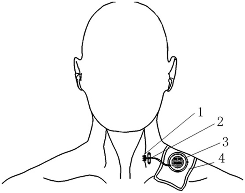
[0018] The electrical stimulation system of the present application can be used to stimulate nerves, blood vessels or other tissues to relieve or treat adverse symptoms of patients, or stimulate damaged nerves to induce their regeneration, or stimulate the vagus nerve to treat hemiplegia, epilepsy, and depression , diabetes, Parkinson's, Alzheimer's disease, cardiovascular and other diseases.

[0019] In this embodiment, the treatment of hemiplegia by stimulating the vagus nerve is taken as an example. The vagus nerve is the nerve with the longest journey and the widest distribution range among the cranial nerves, including four fibers of body movement, somatosensory, visceral motor, and visceral sensation. Hemiplegia is a disease in which one side of the body loses sensory and motor functions due to brain dysfunction caused by brain nerve ...


PUM


Abstract

The invention belongs to the technical field of medical instruments, and particularly relates to a minimally invasive electrical stimulation system. The system comprises a passive implant and a wireless stimulator; the passive implant comprises a stimulation electrode, an ear, a wire and a wireless receiving coil; the stimulation electrode is connected with the wireless receiving coil through the wire; the ear is arranged on the wire close to one side of the stimulation electrode; the wireless stimulator comprises a wireless transmitting coil, a battery, a main control chip, a communication module, a power adjusting module and a frequency adjusting module; the main control chip, the communication module, the power adjusting module and the frequency adjusting module are arranged on a PCB; the power adjusting module and the frequency adjusting module are both in electric signal connection with the main control chip; the power adjusting module and the frequency adjusting module are both adjusted through an impeller button; the main control chip is in electric signal connection with the wireless transmitting coil through the communication module; the battery is in circuit connection with the PCB; and the wireless stimulator is further provided with a charging interface for charging the battery. A passive implantable electrical stimulation mode is adopted, so that the purpose of accurately regulating and controlling the stimulation dosage is achieved, and meanwhile the problem of the battery is solved.

Description

technical field [0001] The application belongs to the technical field of medical devices, and in particular relates to a minimally invasive electrical stimulation system. Background technique [0002] Weak and moderate electrical stimulation can improve or treat some adverse human symptoms. Conventional electrical stimulation is divided into external electrical stimulation and implantable electrical stimulation. In vitro electrical stimulation has little damage, and the regulation process is convenient and safe, without too much consideration of battery power. However, in this stimulation scheme, there is skin and other tissue gaps between the stimulating electrode and the target tissue, and the current cannot be accurately released to the target. area, the effect is greatly weakened. The implantable electrical stimulation implants the stimulating electrodes and the entire stimulating module including the battery into the body, and the electrodes are also in direct contact ...

Claims


Application Information

Patent Timeline
IPC IPC(8): A61N1/36A61N1/372A61N1/375
CPCA61N1/36017A61N1/3605A61N1/36125A61N1/37205A61N1/37223A61N1/375A61N1/3754A61N1/3756A61N1/37518
Inventor 杨全威郭超周国庆单成全
Owner 科斗(苏州)脑机科技有限公司
Why Eureka
Try Eureka