A dehydrogenation reactor cleaning device

A technology of dehydrogenation reactor and cleaning device, applied in the field of cleaning, can solve the problems of low cleaning intensity, influence heat transfer efficiency, high labor intensity of workers, etc., and achieve the effect of ensuring that no residue is left.

Active Publication Date: 2022-03-11
SHANDONG SHENCHI PETROCHEM
View PDF0 Cites 2 Cited by
  • Summary
  • Abstract
  • Description
  • Claims
  • Application Information

AI Technical Summary

Problems solved by technology

[0002] Aiming at the problem of reactor fouling, which seriously affects the heat transfer efficiency, researchers started from two aspects: preventing fouling and removing the fouling layer in time. To prevent fouling, there are ways to improve the arrangement of tubes, optimize the flow rate of the medium, and try to cause pressure pulsation, etc. , but it is still unavoidable to avoid the generation of scale layer; at present, the domestic methods of removing scale layer are mainly mechanical cleaning, chemical cleaning and ultrasonic descaling, each has its advantages and disadvantages, for example, mechanical cleaning is quick but requires disassembly and assembly of equipment, chemical cleaning is more comprehensive but The cleaning intensity is low. Judging from the current trend, ultrasonic descaling will be the hot spot in the future, but it will take time to improve the technology. Chemical cleaning may gradually withdraw from the sight due to its later clean water treatment and other issues. Mechanical cleaning can be used in the next few years. The main problem is that the labor intensity of workers is high, and there are few mechanized technologies in China that can replace manual cleaning work.

Method used


Image

  • A dehydrogenation reactor cleaning device
  • A dehydrogenation reactor cleaning device
  • A dehydrogenation reactor cleaning device

Examples


Embodiment Construction

[0014] In order to make the purpose, technical solutions and advantages of the embodiments of the present invention clearer, the technical solutions in the embodiments of the present invention will be clearly and completely described below in conjunction with the drawings in the embodiments of the present invention. Obviously, the described embodiments It is a part of embodiments of the present invention, but not all embodiments. Based on the embodiments of the present invention, all other embodiments obtained by persons of ordinary skill in the art without creative efforts fall within the protection scope of the present invention.

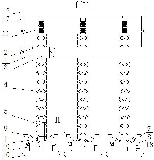
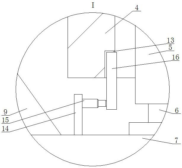
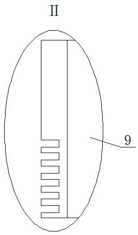
[0015] A dehydrogenation reactor cleaning device, such as Figure 1-4 As shown, including the fixed seat 1, the fixed seat 1 is provided with several through holes 2, and the through holes 2 are all arranged vertically. A reciprocating lead screw 4, the reciprocating lead screw 4 is a tubular structure and the reciprocating lead screw 4 is rotate...


PUM


Abstract

A dehydrogenation reactor cleaning device, the invention belongs to the field of cleaning, comprising a fixed seat, the fixed seat is provided with several through holes, the through holes are all vertically arranged, and the through holes are fixedly installed with a silk nut moving seat, and a silk nut moving seat A reciprocating lead screw passes through the inside, the reciprocating lead screw is a tubular structure and the water supply pipe is installed inside the reciprocating lead screw, the water outlet end of the water supply pipe is connected to the water tank through the rotary joint, the water tank is located under the reciprocating lead screw, and the reciprocating lead screw is vertical For the water tank, several nozzles are installed on the side circumference of the water tank, and the angle between the nozzle and the water tank is less than 90°. The invention cleans the tubes sequentially through three physical cleaning procedures, without dead ends, and can ensure that no residual dirt is left to the greatest extent; the reaction force of the high-pressure jet is fully used to realize the height change of the cleaning procedure, which simplifies the equipment structure and eliminates the need for further cleaning. An additional power source is installed, and when the scale powder enters the tube again, it can form an effect similar to sandblasting.

Description

technical field [0001] The invention belongs to the cleaning field, in particular to a dehydrogenation reactor cleaning device. Background technique [0002] Aiming at the problem of reactor fouling, which seriously affects the heat transfer efficiency, researchers started from two aspects: preventing fouling and removing the fouling layer in time. To prevent fouling, there are ways to improve the arrangement of tubes, optimize the flow rate of the medium, and try to cause pressure pulsation, etc. , but it is still unavoidable to avoid the generation of scale layer; at present, the domestic methods of removing scale layer are mainly mechanical cleaning, chemical cleaning and ultrasonic descaling, each has its advantages and disadvantages, for example, mechanical cleaning is quick but requires disassembly and assembly of equipment, chemical cleaning is more comprehensive but The cleaning intensity is low. Judging from the current trend, ultrasonic descaling will be the hot sp...

Claims


Application Information

Patent Timeline
Patent Type & Authority Patents(China)
IPC IPC(8): B08B9/087B08B9/093
CPCB08B9/087B08B9/093B08B9/0813B08B9/0808
Inventor 宋武生康新成祝书伟刘茂密张晓振
Owner SHANDONG SHENCHI PETROCHEM
Why Eureka
Try Eureka