Automatic detection electric energy meter based on Internet of Things
An automatic detection, Internet of Things technology, applied in the measurement of electrical variables, circuits, relays, etc., can solve the problems of being easily affected by external magnetic fields, not being able to use electricity immediately, and the inconvenience of plug-in electric energy meters. The effect of electric experience, service quality improvement, and stability improvement
- Summary
- Abstract
- Description
- Claims
- Application Information
AI Technical Summary
Problems solved by technology
Method used
Image
Examples
Embodiment approach
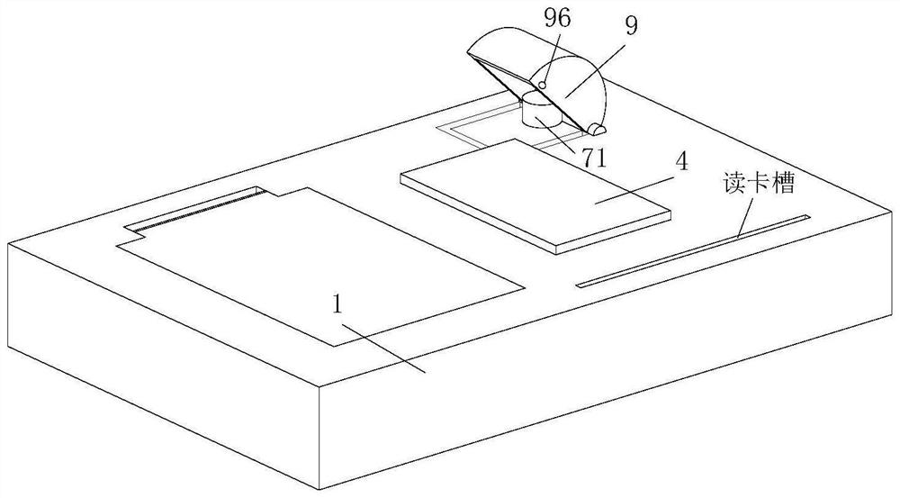
[0056] As an embodiment of the present invention, the relay device 7 includes a round rod 71 , the round rod 71 runs through the outer wall of the housing 1 connected to the display device 4 and is slidingly connected with the housing 1 , and the round rod 71 is located inside the housing 1 One end section is inclined;
[0057] Rectangular block 72 , the rectangular block 72 is slidably connected inside the housing 1 , and one end of the rectangular block 72 facing the round rod 71 is slidably connected with the end of the round rod 71 inside the housing 1 ;
[0058] Connecting rod 79, the connecting rod 79 is located inside the housing 1 and one end of the connecting rod 79 is fixedly connected with the rectangular block 72, and the other end of the connecting rod 79 is fixedly connected with the switch of the relay 3; When opening the relay 3 switch, the user first presses the round rod 71 protruding from the housing 1, and then the round rod 71 moves to the inside of the ho...
Embodiment 1
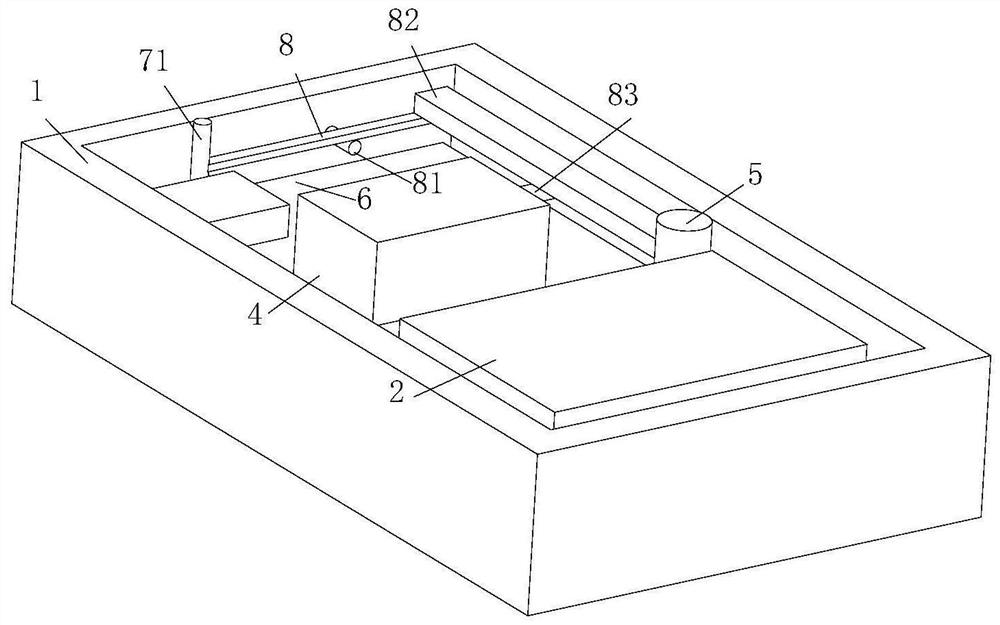
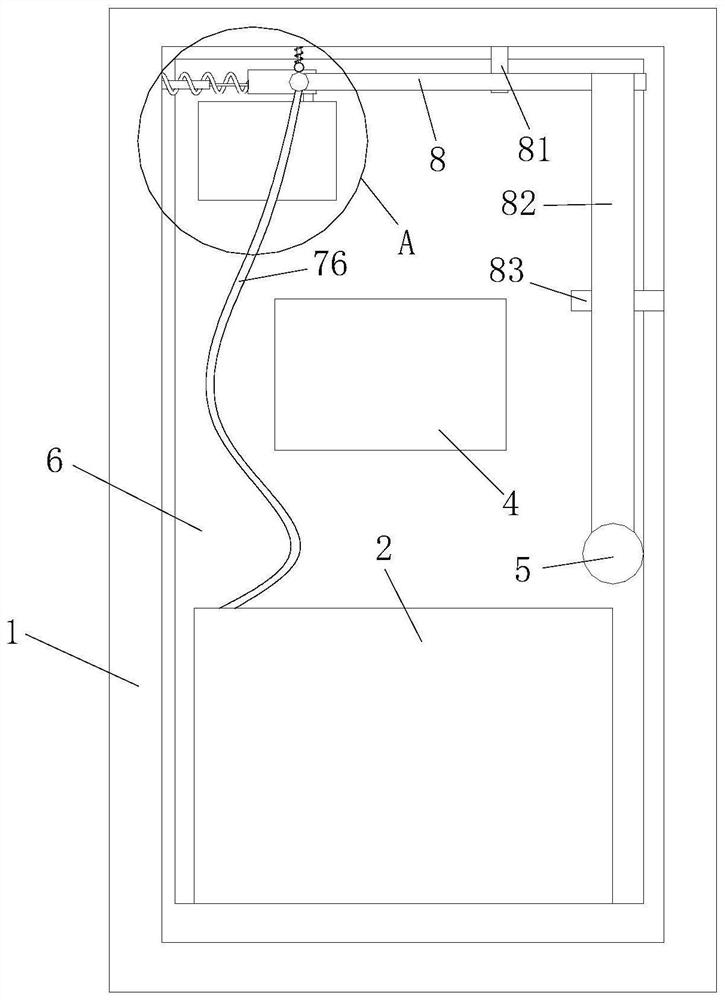
[0067] Embodiment 1: an automatic detection electric energy meter based on the Internet of Things, comprising:
[0068] shell 1;
[0069] The carrier communication module 2, the carrier communication module 2 is located inside the casing 1 and is movably connected with the casing 1, and is used for transmitting and receiving remote signals;
[0070] The relay 3, the relay 3 is fixedly connected inside the casing 1, and is used to control power on and off;
[0071] A display device 4, which is fixedly connected to the surface of the casing 1, and is used to display the power consumption of the user;
[0072] The anti-dismantlement device 5, the anti-dismantlement device 5 is located at the opening of the housing 1 and is slidably connected to the inside of the housing 1 for detecting whether the housing 1 is opened;
[0073] PCB circuit board 6, PCB circuit board 6 is fixedly connected inside the casing 1, and is used for transmitting signals generated by each device;
[007...
Embodiment 2
[0084] The difference between embodiment two and embodiment one is that the inner wall of the circular groove 77 is provided with a pressure sensing plate 78; the pressure sensing plate 78 is connected with the carrier communication module 2 through a wire 76; plate 78 and the pressure sensing plate 78 is connected to the carrier communication module 2 through the wire 76, so that when the user uses the round rod 71 in the power relay device 7, the pressure sensing plate 78 can sense that the ball 731 enters the circular groove 77, and then The pressure sensing board 78 transmits the induction signal to the carrier communication module 2 through the wire 76, and then the carrier communication module 2 transmits the signal to the terminal of the electric power bureau, so that the staff of the electric power bureau can know that the user is using the power extension device 7, and then Send staff to repair the electric energy meter of the user or remind the user to pay in time.
PUM
 Abstract
Description
Claims
Application Information
 - R&D
- Intellectual Property
- Life Sciences
- Materials
- Tech Scout
- Unparalleled Data Quality
- Higher Quality Content
- 60% Fewer Hallucinations
Browse by: Latest US Patents, China's latest patents, Technical Efficacy Thesaurus, Application Domain, Technology Topic, Popular Technical Reports.
© 2025 PatSnap. All rights reserved.Legal|Privacy policy|Modern Slavery Act Transparency Statement|Sitemap|About US| Contact US: help@patsnap.com


