Energy storage system and management method
A technology of energy storage system and management method, which is applied in the field of energy storage system and management, and can solve problems such as peak power consumption and trough power consumption of power supply network
Active Publication Date: 2021-12-14
YUANJIAN WIND POWER JIANGYINENVISION ENERGY CO LTD
10 Cites 0 Cited by
AI-Extracted Technical Summary
Problems solved by technology
[0003] Due to living habits and working hours, the current po...
Abstract
The invention provides an energy storage system and a management method. The energy storage system comprises an energy storage converter, a battery manager and a battery pack; the battery pack comprises at least two groups of battery clusters, wherein the energy storage converter is used for executing charging and discharging current transmitted by the battery manager, the battery manager is used for acquiring the current current of each group of battery clusters, determining the charging and discharging current allowed by the battery pack according to the current current of each group of battery clusters and the limiting current corresponding to each group of battery clusters, and transmitting the acquired charging and discharging current allowed by the battery pack in the next period to the energy storage converter, so that the current flowing through each group of battery clusters in the next period is less than the corresponding limiting current. And the charging and discharging current allowed by the battery pack is obtained through repeated iteration until the current flowing through each group of battery clusters in the next period is less than the corresponding limiting current, and the overcurrent condition is avoided, so the safety of the energy storage system is guaranteed.
Application Domain
Electrical storage systemSingle network parallel feeding arrangements +1
Technology Topic
Electrical batteryProcess engineering +7
Image
Examples
- Experimental program(1)
Example Embodiment
[0041]In order to make the purposes, technical solutions and advantages of the embodiments of the present application clearer, the technical solutions in the embodiments of the present application will be clearly and completely described below in conjunction with the drawings in the embodiments of the present application. Obviously, the described embodiments It is a part of the embodiments of this application, not all of them. The components of the embodiments of the application generally described and illustrated in the figures herein may be arranged and designed in a variety of different configurations.
[0042] Accordingly, the following detailed description of the embodiments of the application provided in the accompanying drawings is not intended to limit the scope of the claimed application, but merely represents selected embodiments of the application. Based on the embodiments in this application, all other embodiments obtained by persons of ordinary skill in the art without creative efforts fall within the protection scope of this application.
[0043] It should be noted that like numerals and letters denote similar items in the following figures, therefore, once an item is defined in one figure, it does not require further definition and explanation in subsequent figures. Meanwhile, in the description of the present application, the terms "first", "second" and the like are only used to distinguish descriptions, and cannot be understood as indicating or implying relative importance.
[0044] It should be noted that in this article, relational terms such as first and second are only used to distinguish one entity or operation from another entity or operation, and do not necessarily require or imply that there is a relationship between these entities or operations. There is no such actual relationship or order between them. Furthermore, the term "comprises", "comprises" or any other variation thereof is intended to cover a non-exclusive inclusion such that a process, method, article, or apparatus comprising a set of elements includes not only those elements, but also includes elements not expressly listed. other elements of or also include elements inherent in such a process, method, article, or device. Without further limitations, an element defined by the phrase "comprising a ..." does not exclude the presence of additional identical elements in the process, method, article or apparatus comprising said element.
[0045] In the description of the present application, it should be noted that the orientation or positional relationship indicated by the terms "upper", "lower", "inner", "outer" etc. is based on the orientation or positional relationship shown in the drawings, or the The usual orientation or positional relationship of the application product when used is only for the convenience of describing the application and simplifying the description, rather than indicating or implying that the referred device or element must have a specific orientation, be constructed and operated in a specific orientation, therefore It should not be construed as a limitation of the application.
[0046] In the description of this application, it should also be noted that, unless otherwise clearly stipulated and limited, the terms "setting" and "connection" should be understood in a broad sense, for example, it can be a fixed connection or a detachable connection, or Integral connection; it can be mechanical connection or electrical connection; it can be direct connection or indirect connection through an intermediary, and it can be the internal communication of two components. Those of ordinary skill in the art can understand the specific meanings of the above terms in this application in specific situations.
[0047] Some implementations of the present application will be described in detail below in conjunction with the accompanying drawings. In the case of no conflict, the following embodiments and features in the embodiments can be combined with each other.
[0048] The electric energy storage system includes multiple battery clusters, and the battery clusters are used to store and release electric energy. It is understandable that the internal resistance of each battery cluster cannot be exactly the same, and the length of the wiring between each battery cluster and the power conversion system (PCS for short) is not exactly the same, that is, the wiring resistance is not exactly the same , and the battery clusters are connected in parallel, so the voltage of the battery clusters is the same. As a result, the values of the discharge current or the charge current of different battery clusters are different. Taking the energy storage system including 3 battery clusters as an example, the rated current corresponding to each battery cluster is 100 mA, and the total rated current of the energy storage system is 300 mA. If the discharge current is 300 mA, the current of each battery cluster is not exactly the same, there must be some battery clusters whose discharge current is greater than 100 mA, and some battery clusters whose discharge current is less than 100 mA. Therefore, there is an overcurrent phenomenon, which has potential safety hazards.
[0049] Continuing to refer to the above example, the discharge current or charging current of the battery clusters is different, and there must be some battery clusters that discharge or charge quickly. Taking the discharge situation as an illustration, some battery clusters may have been fully discharged, and when the battery is empty, some battery clusters are still in a partially discharged state, and there is still a lot of remaining power. But in such a case, it is not possible to continue discharging, but it needs to be charged synchronously, which cannot make good use of the electric energy in other battery clusters, and will cause the capacity of the battery energy storage system to decline too quickly.
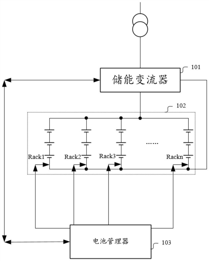
[0050] In order to overcome the above problems, an embodiment of the present application provides an energy storage system. Please refer to figure 1 , figure 1 It is a schematic diagram of the energy storage system architecture provided by the embodiment of this application. The energy storage system includes an energy storage converter 101 , a battery manager 103 and a battery pack 102 , and the battery pack 102 includes at least two groups of battery clusters. Battery clusters such as figure 1 in Rack1, Rack2, Rack3 and Rackn. It should be noted, figure 1 The number of battery clusters shown in is 4, but it is not limited thereto, as long as there are two or more battery clusters.
[0051] Please continue to refer figure 1 , the positive terminal of each battery cluster is connected to the first terminal of the energy storage converter 101, the negative terminal of each battery cluster is connected to the second terminal of the energy storage converter 101, each battery cluster Both are connected to the battery manager 103, and the battery manager 103 is connected to the energy storage converter.
[0052] The energy storage converter 101 is used to implement the charging and discharging current transmitted by the battery manager 103 .
[0053] Specifically, after the energy storage converter 101 receives the charge and discharge current allowed by the battery pack 102 transmitted by the battery manager 103, the energy storage converter 101 can adjust the current of each battery cluster based on its own current distribution logic. , so that the sum of the currents flowing through the battery cluster is equal to the charge and discharge current allowed by the battery pack 102 .
[0054] The battery manager 103 is used to obtain the current current of each battery cluster, and determine the allowable charging and discharging current of the battery pack 102 according to the current current of each battery cluster and the corresponding limit current of each battery cluster, so that the battery pack 102 can flow through The current of each group of battery clusters is less than the corresponding limit current, and the acquired charging and discharging current allowed by the battery group 102 is transmitted to the energy storage converter 101 .
[0055] Understandably, the current current may be an actual charging current or discharging current. Specifically, when the energy storage system is in the charging state, the current current is the charging current, and when the energy storage system is in the discharging state, the current current is the discharging current.
[0056] It can be understood that after the allowable charging and discharging current of the battery pack 102 changes, the current flowing through each battery cluster may change. In a possible implementation, the charge and discharge current allowed by the battery group 102 is obtained repeatedly and iteratively until the current flowing through each group of battery clusters in the next cycle is less than the corresponding limit current. There will be an overcurrent situation, thus ensuring the safety of the energy storage system.
[0057] In summary, the embodiment of the present application provides an energy storage system including an energy storage converter, a battery manager, and a battery pack. The battery pack includes at least two sets of battery clusters, and the positive terminals of each set of battery clusters are connected to The first end of the energy storage converter, the negative end of each group of battery clusters are connected to the second end of the energy storage converter, each group of battery clusters is connected to the battery manager, and the battery manager is connected to the energy storage converter. The energy storage converter is used to execute the charging and discharging current transmitted by the battery manager, and the battery manager is used to obtain the current current of each group of battery clusters, according to the current current of each group of battery clusters and the corresponding The limit current of the battery pack is determined, so that the current flowing through each battery cluster is less than the corresponding limit current, and the obtained charge and discharge current allowed by the battery pack is transmitted to the energy storage converter . After the charge and discharge current allowed by the battery pack changes, the current flowing through each battery cluster may change. Obtain the charge and discharge current allowed by the battery pack until the current flowing through each battery cluster is less than the corresponding limit current, and there will be no overcurrent, thereby ensuring the safety of the energy storage system.
[0058] In a possible implementation, the battery manager 103 is used to acquire the current current of each group of battery clusters, and repeatedly determine the next cycle according to the current current of each group of battery clusters and the corresponding limit current of each group of battery clusters. The charging and discharging current allowed by the internal battery pack 102, so that the current flowing through each group of battery clusters in the next cycle is less than the corresponding limit current, and the obtained charging and discharging current allowed by the battery pack 102 in the next cycle is transmitted to energy storage converter 101.
[0059] In a possible implementation, if it is satisfied that the current flowing through each group of battery clusters in the current cycle is less than the corresponding limit current, and the subsequent limit current does not change, the battery manager 103 may not iterate temporarily, that is The allowable charging and discharging current of the battery pack 102 in the next cycle is not reacquired temporarily. The energy storage converter 101 can perform current conversion work according to the last received charging and discharging current.
[0060] Certainly, the battery manager 103 may repeatedly iterate the charging and discharging current allowed by the battery pack 102 in the next cycle.
[0061] In order to further improve the balance performance and security performance of the storage system, the embodiment of the present application also provides a possible implementation manner, please refer to the following.
[0062] The battery manager 103 is also used to acquire the current limited current of each battery cluster.
[0063] It can be understood that the discharge current or charging current of the battery clusters is different, and after a certain period of time, the remaining power (or, potential energy E) in the battery clusters will change, resulting in that the remaining power in each battery cluster is not completely the same. At this time, the limited current or rated current corresponding to each group of battery clusters will change. In order to further improve the balance performance and safety performance of the storage system, the battery manager 103 needs to obtain the current limited current of each battery cluster. In a possible implementation manner, the current limited current of each battery cluster may be determined according to the current remaining power of each battery cluster.
[0064] Regarding how to determine the allowable charging and discharging current of the battery pack in the next cycle, the embodiment of the present application also provides a possible implementation manner, please refer to the following.
[0065] The battery manager 103 is also used to reduce the total current of the current cycle when the current current of any group of battery clusters is greater than the corresponding limit current, so as to determine the allowable charging and discharging current of the battery group in the next cycle.
[0066] Please continue to refer figure 1 , assuming figure 1 The current currents corresponding to the battery clusters Rack1, Rack2, Rack3 and Rackn in the battery cluster respectively are I 1 , I 2 , I 3 and I n , and the corresponding limiting current is I 1limit , I 2limit , I 3limit and I nlimit. When|I 1 | greater than I 1limit 、|I 2 | greater than I 2limit 、|I 3 | greater than I 3limit and |I n | greater than I nlimit When any one of them is satisfied, it means that there is an overcurrent phenomenon. Therefore, it is necessary to reduce the allowable charging and discharging current of the battery pack 102 in the next cycle. Specifically, the charging and discharging current allowed by the battery pack 102 in the current cycle is reduced. The charge and discharge current allowed by battery pack 102 in the current cycle is I 1 , I 2 , I3 and I n Sum.
[0067] The battery manager 103 is also used to increase the total current of the current cycle when the current current of each battery group is lower than the corresponding limit current, so as to determine the allowable charging and discharging current of the battery group in the next cycle.
[0068] Please continue to refer to the above example, when |I 1 |less than I 1limit 、|I 2 |less than I 21imit 、|I 3 |less than I 3limit and |I n |less than I nlimit When all are met, it means that the battery system is not fully utilized. Therefore, it is necessary to increase the allowable charging and discharging current of the battery pack 102 in the next cycle. Specifically, it is increased on the basis of the charge and discharge current allowed by the battery pack 102 in the current cycle. The charge and discharge current allowed by battery pack 102 in the current cycle is I 1 , I 2 , I 3 and I n Sum.
[0069] Regarding the formula for determining the allowable charging and discharging current of the battery pack in the next cycle, the embodiment of the present application also provides a possible implementation manner, please refer to the following.
[0070] The battery manager 103 determines the allowable charging and discharging current of the battery pack in the next cycle through the following formula;
[0071] I 预总 =|I 总 |-n*max{|I 1 |-I 1limit ,|I 2 |-I 2limit ,...,|I n |-I nlimit};
[0072] Among them, I 总 Characterizes the current cycle total current, I 预总 Characterizes the charge and discharge current allowed by the battery pack in the next cycle, I x Characterizes the current current of the xth battery cluster, I xlimit Represents the limiting current of the xth battery cluster, and n represents the total number of battery clusters.
[0073] Taking the number of battery clusters as 3 as an example, the current currents corresponding to battery clusters Rack1, Rack2, and Rack3 are I 1 , I 2 , I 3 , and the corresponding limiting current is I 1limit , I 2limit , I 3limit. Suppose, I 1limit , I 2limit , I 3limit Both are 100, and I is obtained in the jth cycle 1 =60, I 2 =50, I 3 = 40, I 总 = I 1 +I 2 +I 3 =150.
[0074] I 预总 =|I 总 |-n*max{|I 1 |-I 1limit ,|I 2 |-I 2limit ,...,|I n |-I nlimit};
[0075] I 预总 =150-3*max{(-40), (-50), (-60)}=150+120=270;
[0076] Get I in the j+1th cycle 1 =135, I 2 =90,I 3 = 45, I 总 = I 1 +I 2 +I 3 =270;
[0077] I 预总 =270-3*35=165.
[0078] makes|I k | close to I klimit , and |I q |less than I qlimit ,|I k | is the absolute value of the current of the kth battery cluster with the largest current, |I q |Indicates other battery clusters except the battery cluster of the kth battery cluster.
[0079] Understandably, as the potential energy is released or stored, the maximum difference (|I x |-I xlimit ) The corresponding battery cluster is changing, for I 预总 The affected battery clusters are changing to the extent that each battery cluster can affect the I 预总 , so that the charge or discharge of each battery cluster is balanced to a certain extent; the difference in current between different battery clusters is reduced, and the allowable charge and discharge current of the battery pack in the next cycle is adjusted according to the maximum current value (that is, the PCS rated Current), so that the current value in each battery cluster can be fully released, to avoid the situation of insufficient energy release of the battery cluster.
[0080] Among them, the maximum difference is |I x |-I xlimit The largest value in .
[0081] It can be understood that during the charge and discharge process, each battery cluster is in a parallel state with each other. The voltage of each cell cluster pair is the same. However, with the charging and discharging of currents of different magnitudes, the remaining power of each battery cluster is different, so the potential energy E of each battery cluster is different.
[0082] Please refer to the following formula, in charging state: U=E-IR; in discharging state: U=E+IR.
[0083] In order to keep the voltage of each battery cluster the same, the corresponding current value of the battery cluster of potential energy E will be reduced. That is, the maximum difference (|I x |-I xlimit ) The corresponding battery cluster is changing.
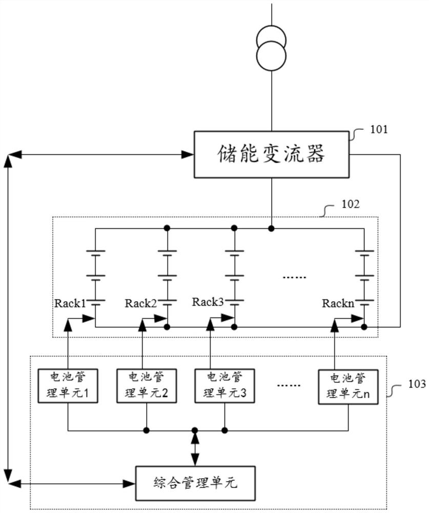
[0084] Please refer to figure 2 , regarding the composition of the battery manager 103, the embodiment of the present application also provides a possible implementation manner. like figure 2 As shown, the battery manager 103 includes at least two groups of battery management units (referred to as RBMS) and a group of integrated management units (abbreviated as BBMS). The number of battery management units is the same as the number of battery clusters, and each group of battery management units is respectively It is connected with the corresponding battery cluster, each group of battery management units is connected with the comprehensive management unit, and the comprehensive management unit is connected with the energy storage converter 101 .
[0085] The battery management unit RBMS is used to obtain the performance parameters of the corresponding battery cluster, such as the current remaining power, the current current, the current limited current, and the current temperature. And transmit the collected performance parameters to the comprehensive management unit BBMS.
[0086] The comprehensive management unit BBMS is used to determine the allowable charging and discharging current of the battery pack 102 in the next cycle.
[0087] In a possible implementation manner, the energy storage converter 101 is connected to an external main grid through a transformer, so that the energy storage system can complete storage and release of electric energy.
[0088] It should be noted that in the embodiment of the present application, the battery clusters are connected in parallel, that is, the voltages at both ends of each battery cluster are the same. Those skilled in the art can know the relationship between power and voltage and current. In the case of the same voltage, the limitation on current can be equivalent to the limitation on power. Therefore, the current current in the embodiment of the present application may be equal to the current power, the current limit may be equal to the power limit, and the charge and discharge current may be equal to the charge and discharge power, which will not be repeated here.
[0089] It should be understood that figure 1 and figure 2 The structure shown is only a structural schematic diagram of a part of the energy storage system, and the energy storage system may also include figure 1 and figure 2 more or fewer components than shown in, or with figure 1 and figure 2 Different configurations are shown. figure 1 and figure 2 Each component shown in can be realized by hardware, software or a combination thereof.
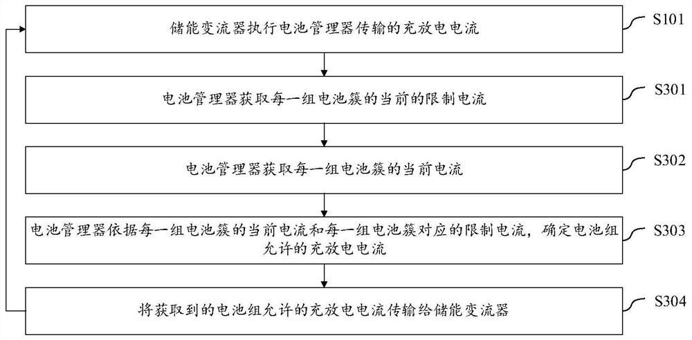
[0090] An energy storage system management method provided in the embodiment of this application can be applied to, but not limited to figure 1 and figure 2 The electronic equipment shown, the specific process, please refer to image 3 , the energy storage system management methods include:
[0091] S101, the energy storage converter executes the charging and discharging current transmitted by the battery manager.
[0092] S302. The battery manager acquires the current current of each battery cluster.
[0093] S303. The battery manager determines the allowable charging and discharging current of the battery pack according to the current current of each battery cluster and the corresponding limit current of each battery cluster.
[0094] S304, transmitting the acquired charging and discharging current allowed by the battery pack to the energy storage converter.
[0095] In a possible implementation manner, after S304 is executed, S101 may be repeatedly executed, so that the current flowing through each group of battery clusters in the next cycle is smaller than the corresponding limited current.
[0096] In a possible implementation manner, S303, the battery manager determines the allowable charging and discharging current of the battery pack in the next cycle according to the current current of each battery cluster and the corresponding limit current of each battery cluster. S304, transmitting the acquired charge and discharge current allowed by the battery pack in the next cycle to the energy storage converter.
[0097] Please continue to refer image 3 , in a possible implementation manner, the energy storage system management method further includes:
[0098] S301. The battery manager acquires the current limited current of each battery cluster.
[0099] It should be noted that the embodiment of the present application does not limit the execution order of S302 and S301, and the two may be executed simultaneously or separately.
[0100] exist image 3 Based on the content in S103, the embodiment of this application also provides a possible implementation, please refer to Figure 4 , S103 includes:
[0101] S103-1. When the current current of any group of battery clusters is greater than the corresponding limit current, the battery manager reduces the total current of the current cycle to determine the allowable charging and discharging current of the battery group in the next cycle.
[0102] S 103-2. When the current current of each battery cluster is lower than the corresponding limit current, the battery manager increases the total current of the current cycle to determine the allowable charging and discharging current of the battery group in the next cycle.
[0103]In a possible implementation, the battery manager determines the allowable charging and discharging current of the battery pack in the next cycle through the following formula;
[0104] I 预总 =|I 总 |-n*max{|I 1 |-I 1limit ,|I 2 |-I 2limit ,...,|I n |-I nlimit};
[0105] Among them, I 总 Characterizes the current cycle total current, I 预总 Characterizes the charge and discharge current allowed by the battery pack in the next cycle, I x Characterizes the current current of the xth battery cluster, I xlimit Represents the limiting current of the xth battery cluster, and n represents the total number of battery clusters.
[0106] In a possible implementation, the battery manager includes at least two groups of battery management units and a group of integrated management units, the number of battery management units is the same as the number of battery clusters, and each group of battery management units is connected to the corresponding battery cluster Each group of battery management units is connected to the integrated management unit, and the integrated management unit is connected to the energy storage converter.
[0107] It should be noted that the energy storage system management method provided in this embodiment can perform the functions and purposes of each part in the above energy storage system embodiments, so as to achieve corresponding technical effects. For brief description, for parts not mentioned in this embodiment, reference may be made to the corresponding content in the foregoing embodiments.
[0108] The above descriptions are only preferred embodiments of the present application, and are not intended to limit the present application. For those skilled in the art, there may be various modifications and changes in the present application. Any modifications, equivalent replacements, improvements, etc. made within the spirit and principles of this application shall be included within the protection scope of this application.
[0109] It will be apparent to those skilled in the art that the present application is not limited to the details of the exemplary embodiments described above, but that the present application can be implemented in other specific forms without departing from the spirit or essential characteristics of the present application. Therefore, the embodiments should be regarded as exemplary and not restrictive in all points of view, and the scope of the application is defined by the appended claims rather than the foregoing description, and it is intended that the scope of the present application be defined by the appended claims rather than by the foregoing description. All changes within the meaning and range of equivalents of the elements are embraced in this application. Any reference sign in a claim should not be construed as limiting the claim concerned.
PUM


Description & Claims & Application Information
We can also present the details of the Description, Claims and Application information to help users get a comprehensive understanding of the technical details of the patent, such as background art, summary of invention, brief description of drawings, description of embodiments, and other original content. On the other hand, users can also determine the specific scope of protection of the technology through the list of claims; as well as understand the changes in the life cycle of the technology with the presentation of the patent timeline. Login to view more.