
Clock synchronization system

A clock synchronization and clock technology, applied in the direction of time division multiplexing system, electrical components, multiplexing communication, etc., can solve the problem that the clock source is difficult to apply

Pending Publication Date: 2021-12-14
SUZHOU GUANGGE EQUIP
View PDF0 Cites 0 Cited by
  • Summary
  • Abstract
  • Description
  • Claims
  • Application Information

AI Technical Summary

Problems solved by technology

However, due to the complexity of the laying environment of transmission lines in various places, especially mixed lines, the same type of clock source is difficult to apply

Method used


Image

  • Clock synchronization system
  • Clock synchronization system
  • Clock synchronization system

Examples


Embodiment Construction

[0033] In order to make the purpose, technical solution and advantages of the present application clearer, the present application will be further described in detail below in conjunction with the accompanying drawings and embodiments. It should be understood that the specific embodiments described here are only used to explain the present application, and are not intended to limit the present application.

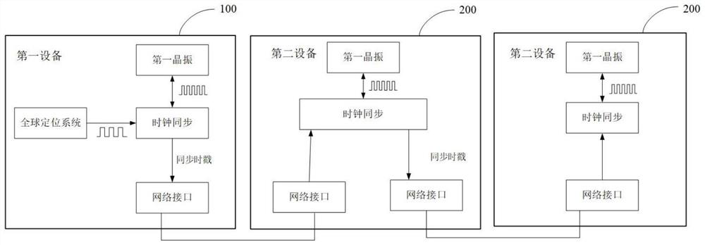
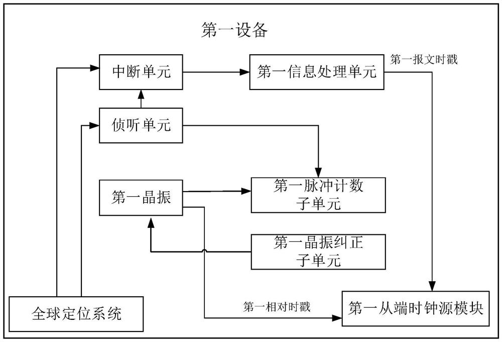
[0034] In one of the examples, as figure 1 As shown, a clock synchronization system is provided, and the clock synchronization system includes: at least one first device 100 and at least one second device 200 . Wherein, at least one first device 100 and at least one second device 200 are sequentially connected through a network interface. Preferably, the network interfaces are connected through optical fibers. One thing that needs to be explained is that the combination of figure 2 , where the ordering of the first device 100 and the second device 200 can be arbitrary,...


PUM


Abstract

The invention relates to a clock synchronization system. The clock synchronization system comprises: at least one first device configured to perform clock synchronization through using a global positioning system and a time synchronization protocol; and at least one second device configured to perform clock synchronization through using a time synchronization protocol; wherein the at least one first device is sequentially connected with the at least one second device through a network interface, the first device performs clock synchronization through the global positioning system, and the second device connected with the first device takes a clock synchronized by the first device as a main clock source; and when the at least one second device is connected behind the second device, each second device performs clock synchronization by taking the clock synchronized by the previous second device as a main clock source until the clock synchronization of all the second device is completed. By adopting the clock synchronization system, a high-precision clock synchronization mode of the devices can be realized step by step.

Description

technical field [0001] The present application relates to the technical field of power detection, in particular to a clock synchronization system. Background technique [0002] With the development of power detection technology, the NTP Ethernet timing method has appeared. The general NTP Ethernet timing method has only millisecond-level synchronization accuracy. The monitoring equipment of the terminal has a precise synchronous clock source, so the NTP Ethernet timing method is far from meeting the needs of precise positioning. [0003] Based on this, the GNSS synchronous clock source is generally used in occasions where outdoor wireless communication is good, and the PTP optical fiber synchronous clock source is generally used in cable tunnels and other occasions. However, due to the complexity of the laying environment of transmission lines in various places, especially mixed lines, the same type of clock source is difficult to apply. Therefore, it is of great significa...

Claims


Application Information

Patent Timeline
IPC IPC(8): H04J3/06
CPCH04J3/0638H04J3/0644
Inventor 韩叶祥钱俊波王宏飞姜明武
Owner SUZHOU GUANGGE EQUIP
Learn More