Supercharge Your Innovation With Domain-Expert AI Agents!

Energy storage charging pile for energy storage battery

A technology for energy storage batteries and charging piles, which is applied in the direction of electric vehicle charging technology, charging stations, and vehicle energy storage. It can solve the problems of inconvenient charging cables and charging gun head protection, complicated handling of charging piles, and reduced service life. Achieve the effect of saving manpower, moving conveniently and increasing the service life

Pending Publication Date: 2021-12-17
四川嘉义新能有限公司
View PDF0 Cites 0 Cited by
  • Summary
  • Abstract
  • Description
  • Claims
  • Application Information

AI Technical Summary

Problems solved by technology

[0004] General smart AC charging piles are used outdoors, it is inconvenient to protect the charging cable and charging head, which will cause the charging cable and charging head to be exposed to the outside world for a long time, which will be easily damaged and reduce the service life. The protective structure is added to the cable and the charging head, which is convenient for better protection of the charging cable and the charging head, so that the charging cable and the charging head are not easy to be damaged, and the service life of the charging cable and the charging head is increased, and the handling of the charging pile is relatively easy. It is cumbersome, so it is necessary to improve the structure of the charging pile. At the same time, the present invention provides an energy storage charging pile for an energy storage battery, which is convenient to better solve the above-mentioned problems

Method used


Image

  • Energy storage charging pile for energy storage battery
  • Energy storage charging pile for energy storage battery
  • Energy storage charging pile for energy storage battery

Examples


Embodiment Construction

[0025] In order to make the object, technical solution and advantages of the present invention clearer, the present invention will be further described in detail below in conjunction with the accompanying drawings and embodiments. It should be understood that the specific embodiments described here are only used to explain the present invention, not to limit the present invention.

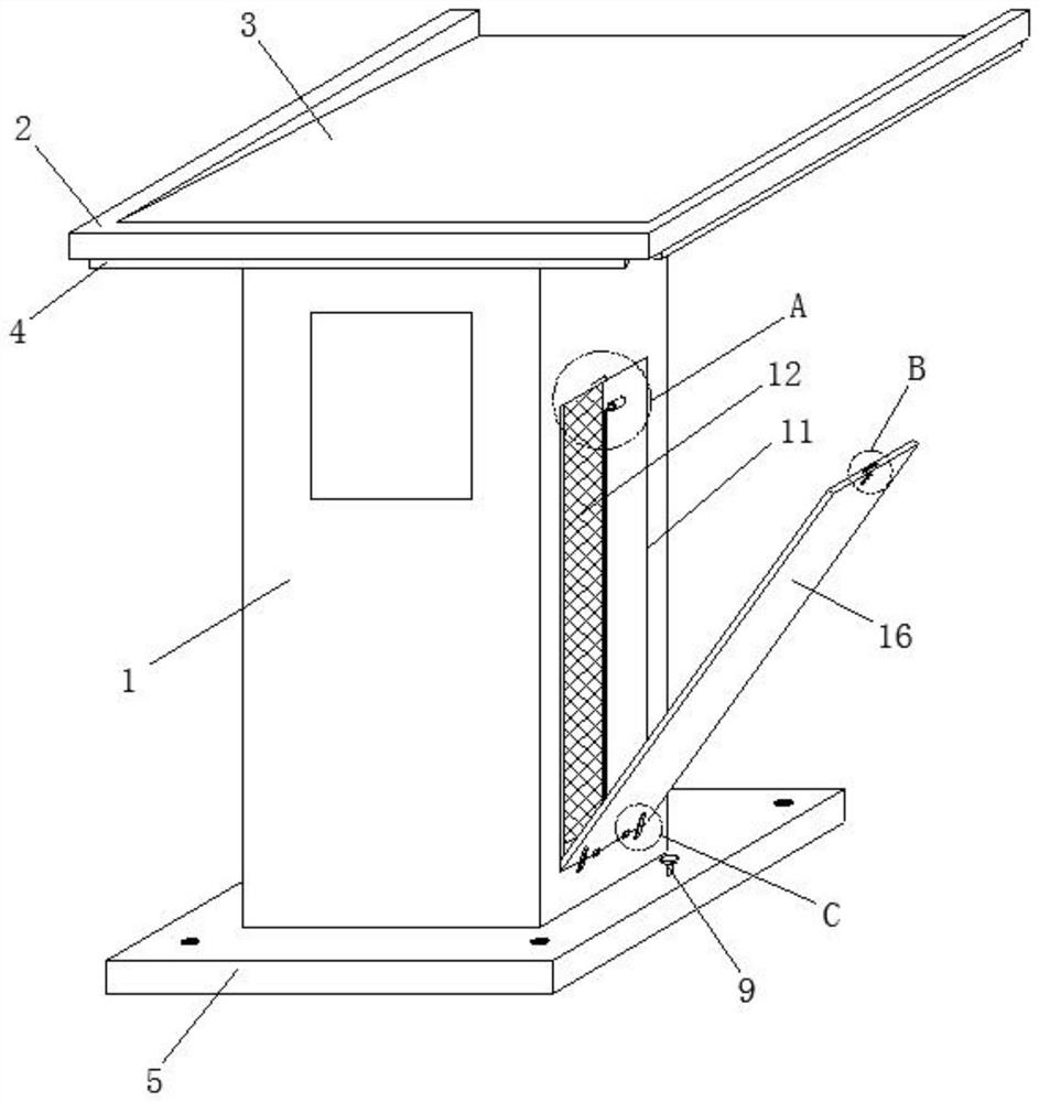
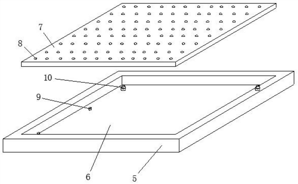
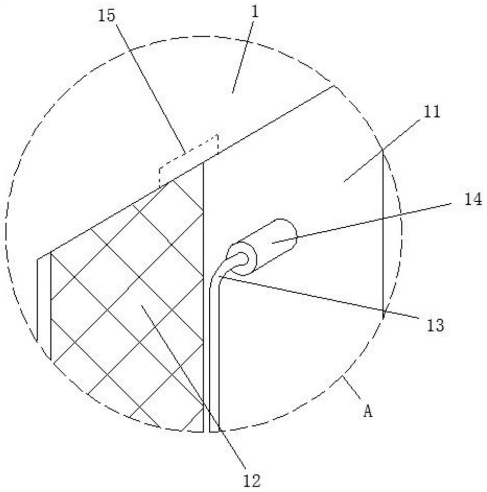
[0026] refer to figure 1 and figure 2 As shown, an energy storage charging pile for an energy storage battery includes a charging pile 1 and a waterproof top cover 2 fixedly connected to the top of the charging pile 1, so that the charging pile 1 can be waterproofed through the waterproof top cover 2, and the waterproof top cover 2 There is a drainage groove 3 in the top, the bottom of the drainage groove 3 is an inclined structure, and the rear of the drainage groove 3 is an open structure, so that the rainwater drainage groove can be passed through the drainage groove 3 behind the charging pile...


PUM


Abstract

The invention discloses an energy storage charging pile for energy storage battery; the pile comprises a charging pile body, a waterproof top cover is fixedly connected to the top of the charging pile body, a drainage groove is formed in the top of the waterproof top cover, an illuminating lamp is arranged below the waterproof top cover, and a mounting base is fixedly connected to the bottom of the charging pile body; a positioning groove is formed in the mounting base, a positioning plate is inserted into the positioning groove, a bull eye bearing is arranged on the positioning plate, screw rods are in threaded connection with the two sides of the bottom end in the positioning groove, the screw rods are rotationally mounted in the positioning plate, and a telescopic rod is fixedly connected to the bottom end of the bottom of the positioning groove. And the end, away from the bottom end in the positioning groove, of the telescopic rod is fixedly connected with the positioning plate, so that a charging wire and a charging gun head can be better stored, the charging wire and the charging gun head are not prone to being damaged, and the service life of the charging wire and the charging gun head is prolonged; meanwhile, the charging pile is convenient to move, manpower is saved, and the working efficiency is improved.

Description

technical field [0001] The invention belongs to the technical field of energy storage charging piles, in particular to an energy storage charging pile for energy storage batteries. Background technique [0002] The function of the charging pile is similar to the refueling machine in the gas station. It can be fixed on the ground or wall, and installed in public buildings (public buildings, shopping malls, public parking lots, etc.) and residential area parking lots or charging stations. Charge all models of electric vehicles. The input end of the charging pile is directly connected to the AC grid, and the output end is equipped with a charging plug for charging the electric vehicle. Charging piles generally provide two charging methods: conventional charging and fast charging. People can use a specific charging card to swipe the card on the human-computer interaction interface provided by the charging pile to perform corresponding charging methods, charging time, and cost d...

Claims


Application Information

Patent Timeline
Patent Type & Authority Applications(China)
IPC IPC(8): B60L53/31B60L53/302B60L53/14F21V33/00
CPCB60L53/31B60L53/302B60L53/14F21V33/00Y02T10/70Y02T10/7072Y02T90/12Y02T90/14
Inventor 赵靖闵敏
Owner 四川嘉义新能有限公司
Features
  • R&D
  • Intellectual Property
  • Life Sciences
  • Materials
  • Tech Scout
  • Unparalleled Data Quality
  • Higher Quality Content
  • 60% Fewer Hallucinations
Learn More