Sinking switch type floor drain

A switch-type, floor-drain technology, applied in the direction of fixed filter element, separation method, filtration separation, etc., can solve the problems of being stuck in the gap between the upper cover and the base, easily kicked by the toes, and troublesome to operate, etc. Achieve the effect of easy standardized preparation, reduced installation requirements, and convenient installation

Pending Publication Date: 2021-12-17
NINGBO BOSHENG PLUMBING CO
View PDF0 Cites 0 Cited by
  • Summary
  • Abstract
  • Description
  • Claims
  • Application Information

AI Technical Summary

Problems solved by technology

Since the floor drain is normally open, the toes are easy to kick or get stuck in the gap between the upper cover and the base, causing injury
For the floor drain of this structure, it is recommended to connect the filter screen to the base with screws or threads to provide a stable bottom connection, but this requires the use of tools to disassemble and assemble. to disassemble

Method used


Image

  • Sinking switch type floor drain
  • Sinking switch type floor drain
  • Sinking switch type floor drain

Examples


Embodiment Construction

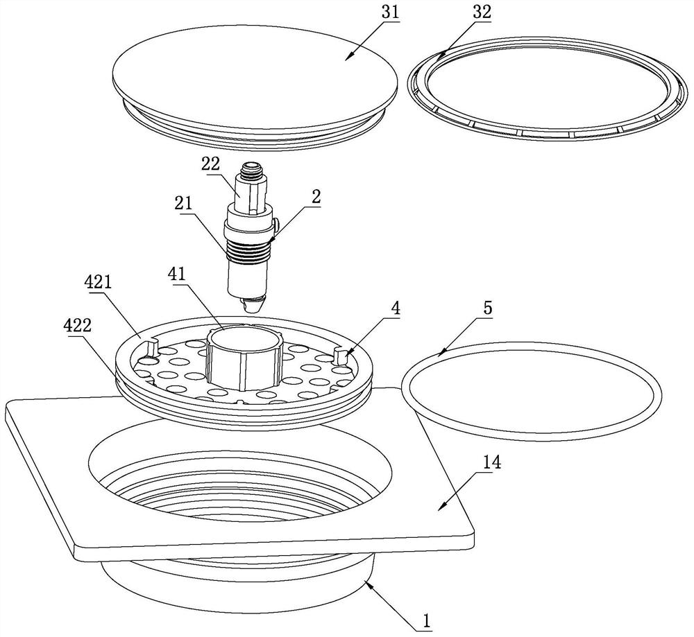
[0019] Refer to attached picture. The sinking switch type floor drain provided by the present invention includes a floor drain base 1 , a filter screen 4 , an upper cover device and a switch device 2 , and the floor drain base 1 has an inner hole 10 and a top mounting surface 14 . The base of the floor drain is connected to the applied ground or the bottom surface of the integral bathroom, and can be connected by bonding.

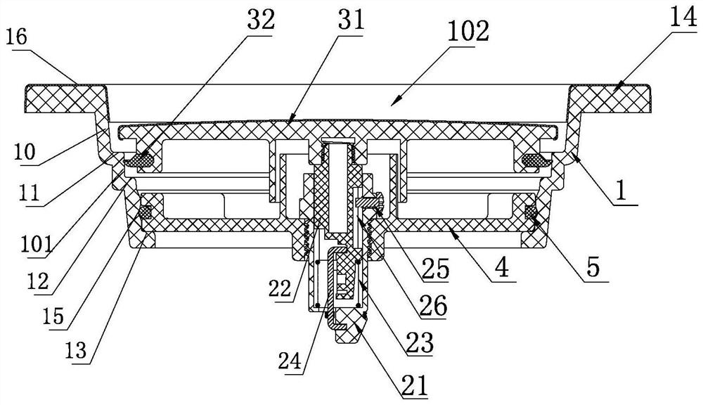
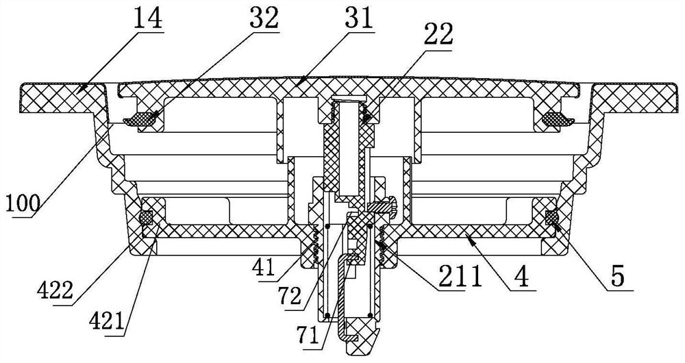
[0020] The switch device 2 includes a fixed part 21, an up and down moving part 22 and a jacking spring 23 thereof. The fixed part has a guide hole 211 for the up and down moving part 22 to move up and down. Jacking spring 23.

[0021] The upper cover device includes an upper cover 31 and a sealing ring 32 , wherein the upper cover 31 is screwed to the top of the up and down moving part 22 .

[0022] A lifting control mechanism is set between the fixed part 21 and the up and down moving part 22. The lifting control mechanism provides two stop positions up...


PUM


Abstract

The invention provides a sinking switch type floor drain. The sinking switch type floor drain comprises a floor drain base, a filter screen, an upper cover device and a switch device, a first annular step and a second annular step are arranged on the inner hole wall of the floor drain base, the first annular step is located above the second annular step, and through the control of a lifting control mechanism, the upper cover device operates in the space between the first annular step and a flange face and the inner hole space below the second step face, ascends to the opening position and descends to the closing position. The sinking switch type floor drain has no use safety risk, has lower mounting requirements, is easy to mount and dismount, and can recover the water seal function of the floor drain by using the structure of the floor drain during use.

Description

technical field [0001] The invention relates to a floor drain. Background technique [0002] The floor drain with switch function on the market has a switch mechanism inside, the fixed seat of the switch mechanism is connected to the filter screen, and the top of the lifting shaft of the switch structure is connected to the upper cover. When operating, press once to close the floor drain, and press again to open the floor drain. Current floor drains of this type need to drain water from the gap between the upper cover that is higher than the ground (the top mounting surface of the base) and the base below it when the floor drain is opened, that is, when the floor drain is closed, the upper cover is basically in contact with the ground (the base) The top installation surface of the base) is flat, and when the floor drain is opened, the upper cover is raised above the ground (the top installation surface of the base) at a certain height. Since the floor drain is normally ope...

Claims


Application Information

Patent Timeline
Patent Type & Authority Applications(China)
IPC IPC(8): E03F5/04B01D35/02B01D29/01B01D29/96
CPCE03F5/0407B01D35/02B01D29/01B01D29/96
Inventor 岑迪峰
Owner NINGBO BOSHENG PLUMBING CO
Why Eureka
Try Eureka