Anti-theft detection method for vehicle based on RFID and baroceptor technology

An air pressure sensor, vehicle anti-theft technology, applied in the direction of anti-theft vehicle accessories, vehicle parts, instruments, etc., can solve the problems of complex installation, loss of free maintenance, long time, etc., and achieve the effect of reducing installation requirements and reducing damage

Active Publication Date: 2008-04-02
XIAMEN YAXON NETWORKS CO LTD
View PDF0 Cites 13 Cited by
  • Summary
  • Abstract
  • Description
  • Claims
  • Application Information

AI Technical Summary

Problems solved by technology

[0002] With the popularization of vehicles, people have higher and higher requirements for anti-theft vehicles, followed by people's requirements for anti-theft functions of vehicles are also increasing day by day. Now the detection method used by common anti-theft devices is the same as the sensor on the car. Signals are connected, such as detecting signals such as car doors, lights, and ACC. For different models, the installation positions of the door, ACC, lights and other signals are different for each model, which requires the installers to be familiar with the electrical connection diagrams of each model, and requires relatively high skills for the installers. A vehicle often takes a long time
On the other hand, each new car has a maintenance period for a period of time. During the maintenance period, the car owner can obtain free vehicle maintenance from the manufacturer. However, if the car owner changes the electrical wiring of the vehicle without the manufacturer's permission during the maintenance period, it may As a result, the manufacturer refuses to provide free maintenance for the vehicle, so if the owner wants to install an anti-theft alarm on the new car, he may face the danger of losing the free maintenance
To sum up, the main disadvantage of the anti-theft detection method connected with the vehicle sensor signal is that there are many connections, complicated installation, and certain damage to the electrical connection of the original vehicle.

Method used


Image

  • Anti-theft detection method for vehicle based on RFID and baroceptor technology
  • Anti-theft detection method for vehicle based on RFID and baroceptor technology
  • Anti-theft detection method for vehicle based on RFID and baroceptor technology

Examples


Embodiment Construction

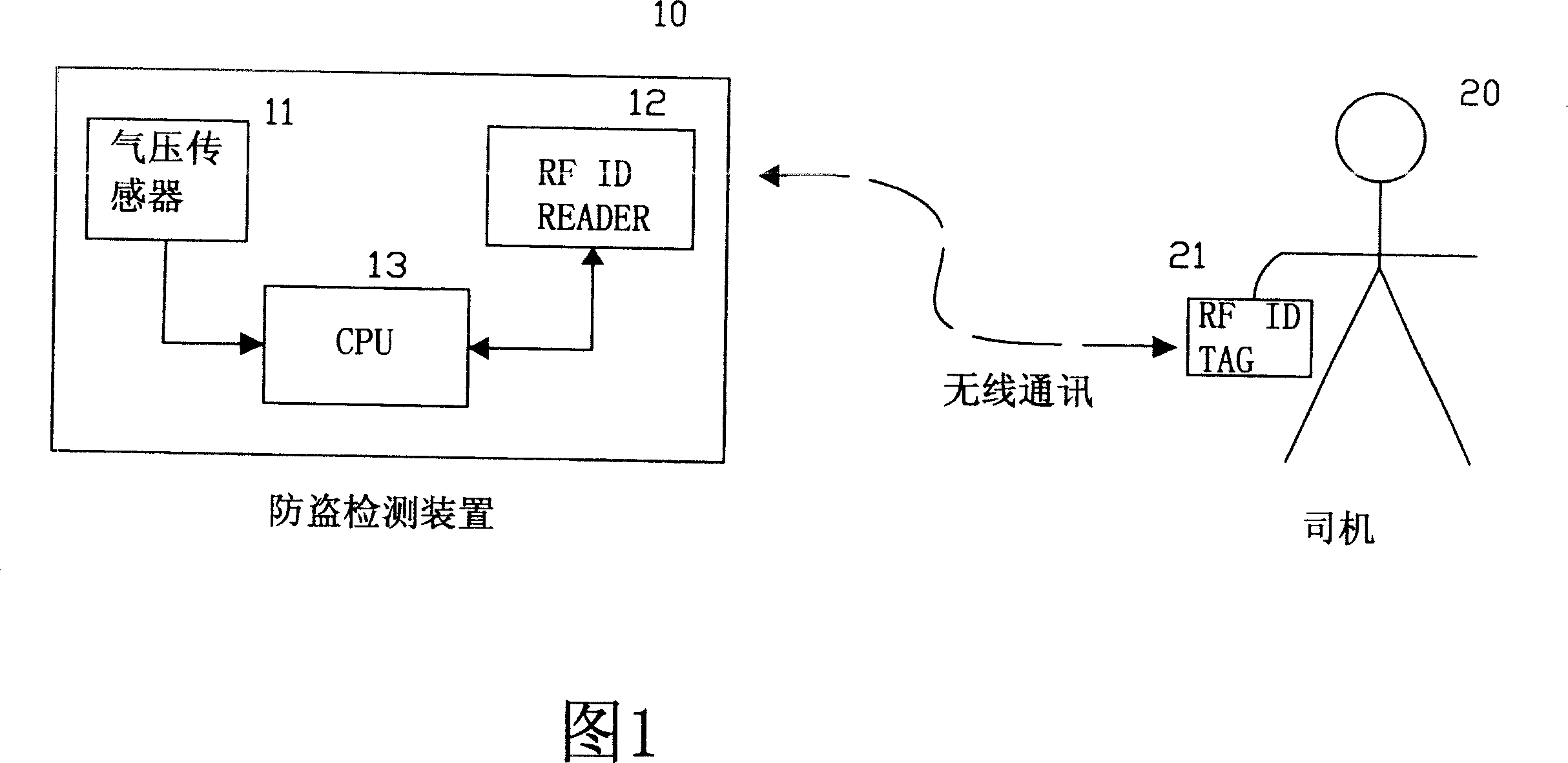
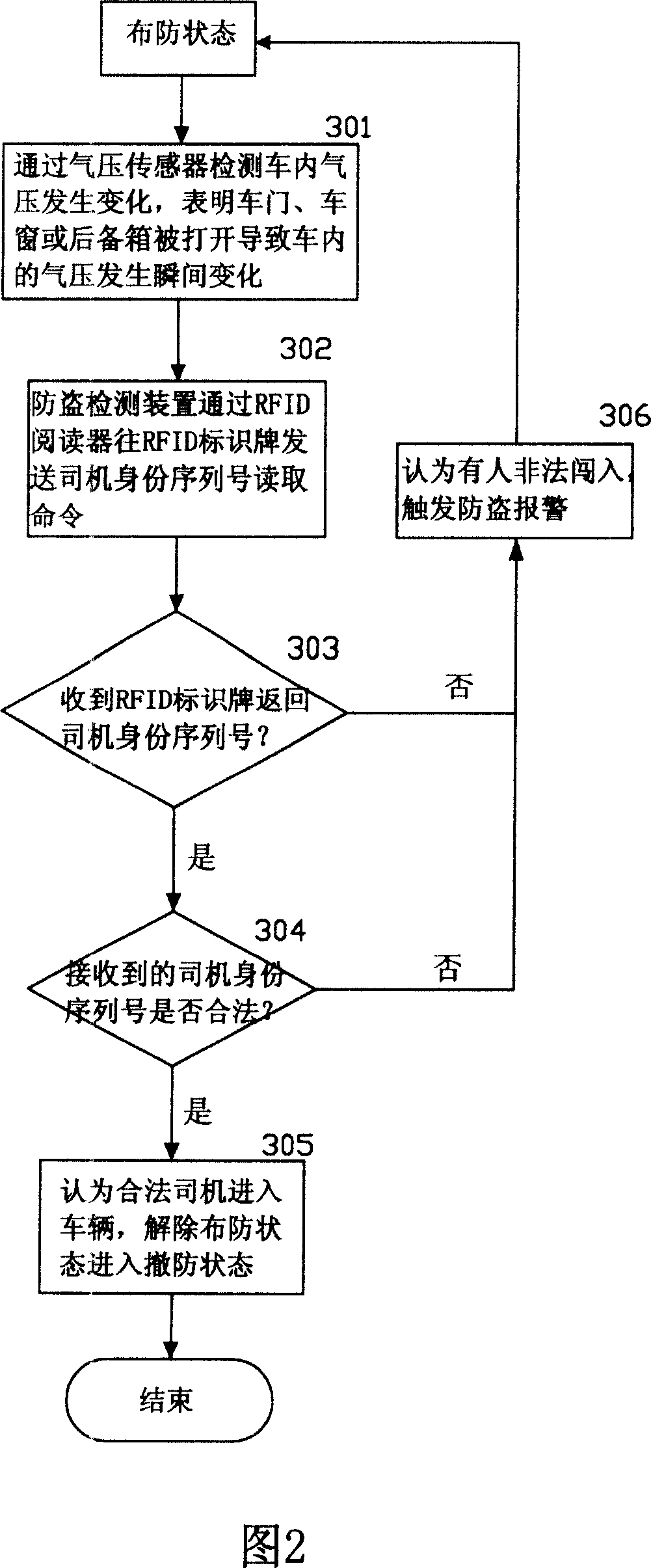
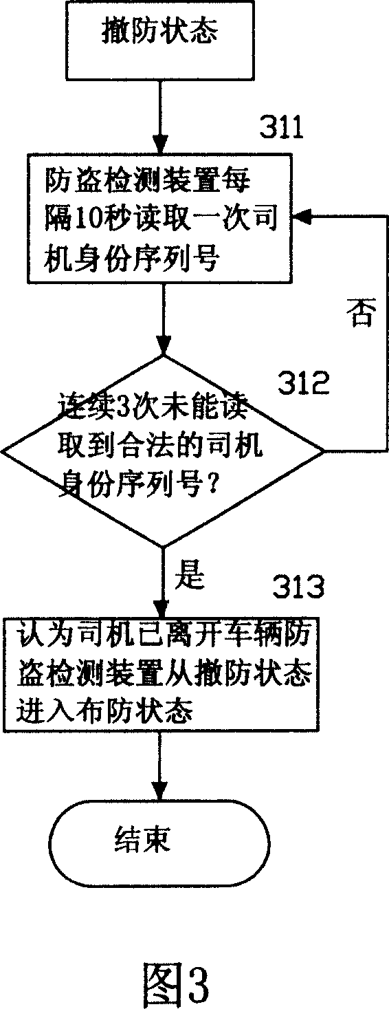
[0024] Fig. 1 is a schematic diagram of the composition of the device for realizing the method of the present invention, the device for realizing the method of the present invention includes an anti-theft detection device 10 installed in the vehicle and an RFID tag 21 carried on the driver 20, and the anti-theft detection device 10 is centrally processed by the CPU Device 13, air pressure sensor 11, RFID reader 12 constitute, the signal of air pressure sensor 11 is input to CPU central processing unit 13 after analog / digital conversion, CPU central processing unit 13 is connected with RFID reader 12, RFID reader 12 and Wireless communication between RFID identification plates 21 is realized through radio frequency technology. RFID reader 12 is responsible for carrying out wireless communication with RFID identification plate 21, reads the ID sequence number stored on RFID identification plate 21, is used for judging whether the driver's identity is legal. The air pressure sens...


PUM


Abstract

The present invention discloses a pressure sensor based on RFID technology and a vehicle anti-theft detection technique. An instantaneous pressure change in the car is detected by the pressure sensor. When the pressure changes, an identity serial number of a driver marked in a mark card can be read by an anti-theft detection device through a RFID reader. The decision of whether driving an alarming device to alarm is made after judging the legality of the serial number of the driver. At the same time, the identity serial number of the driver is read by RFID at a fixed interval (such as 10 seconds); the driver is judged as having left the car if the legal identity serial number of the driver for a continuous fixed times (such as 3 times), and then the defending state is shifted from 'off' to 'on'. Destructive operations, such as cutting an electrical connection line from the original car are not necessary. The present invention has the advantages of simple and convenient in installation; and reliable in anti-theft detection. The present invention is characterized in easy to use and prevail thus is suitable for any car model.

Description

technical field [0001] The invention relates to a vehicle anti-theft detection method based on RFID and air pressure sensor technology. Background technique [0002] With the popularization of vehicles, people have higher and higher requirements for anti-theft vehicles, followed by people's requirements for anti-theft functions of vehicles are also increasing day by day. Now the detection method used by common anti-theft devices is the same as the sensor on the car. Signals are connected, such as detecting signals such as car doors, lights, and ACC. For different models, the installation positions of the door, ACC, lights and other signals are different for each model, which requires the installers to be familiar with the electrical connection diagrams of each model, and requires relatively high skills for the installers. A vehicle often takes a long time. On the other hand, each new car has a maintenance period for a period of time. During the maintenance period, the car ...

Claims


Application Information

Patent Timeline
Patent Type & Authority Applications(China)
IPC IPC(8): B60R25/00G07C11/00B60R25/10B60R25/31
Inventor 陈从华汤益明杨磊任赋韦昌荣
Owner XIAMEN YAXON NETWORKS CO LTD
Why Eureka
Try Eureka