
Scattering-medium-through non-invasive optical imaging and positioning device and method

An optical imaging and medium technology, applied in the direction of optical devices, measuring devices, image analysis, etc., can solve the problems of inability to determine the position and actual size, and inability to realize real-time non-destructive imaging

Pending Publication Date: 2021-12-17
SHANGHAI INST OF OPTICS & FINE MECHANICS CHINESE ACAD OF SCI
View PDF0 Cites 2 Cited by
  • Summary
  • Abstract
  • Description
  • Claims
  • Application Information

AI Technical Summary

Problems solved by technology

Among them, optical phase conjugation, iterative wavefront shaping, scattering matrix measurement, and speckle deconvolution imaging all need to introduce reference points or reference objects for pre-measurement, which cannot achieve real-time non-destructive imaging
In the absence of auxiliary information, all these methods can only recognize the shape of the object, but cannot determine its position and actual size

Method used


Image

  • Scattering-medium-through non-invasive optical imaging and positioning device and method
  • Scattering-medium-through non-invasive optical imaging and positioning device and method

Examples


Embodiment Construction

[0019] The following is a detailed description of the embodiments of the present invention: this embodiment is implemented on the premise of the technical solution of the present invention, and provides detailed implementation methods and specific operation processes. It should be noted that those skilled in the art can make several modifications and improvements without departing from the concept of the present invention, and these all belong to the protection scope of the present invention.

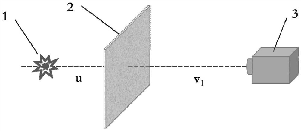
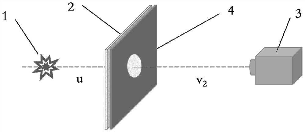
[0020] see figure 2 , figure 2 It is a structural schematic diagram of the non-invasive optical imaging and positioning through the scattering medium of the present invention. As shown in the figure, a device for non-invasive optical imaging and positioning through the scattering medium includes a scattering medium layer 2, a diaphragm 4 and a CCD A camera 3, the aperture 4 is located between the scattering medium layer 2 and the CCD camera 3, and is close to the scattering medium la...


PUM


Abstract

A scattering-medium-through non-invasive optical imaging and positioning device comprises a scattering medium layer, a diaphragm and a CCD camera, the diaphragm is located between the scattering medium layer and the CCD camera and tightly attached to the scattering medium layer, the CCD camera can be used for recognizing the complete envelope of speckle pattern intensity distribution and the size of each speckle particle, and an object to be measured, the scattering medium layer, the diaphragm and the CCD camera share the same optical axis; Tnvention further provides a non-invasive optical imaging and positioning method. According to the method, no auxiliary means or information behind a scattering medium is needed, there is completely no invasion, all information can be extracted through single exposure, and real-time lossless optical imaging can be carried out. The method and device have wide potential application in the aspects of biological tissue optical imaging, fluorescence imaging, anti-terrorism monitoring, underwater scanning and the like.

Description

technical field [0001] The invention belongs to the technical field of speckle autocorrelation imaging, and in particular relates to an optical imaging and positioning device and method through a scattering medium. Background technique [0002] When the light emitted by an object passes through a medium such as a shower curtain, frosted glass, or biological tissue, due to its internal non-uniformity, the light scatters multiple times, and the wavefront is completely randomized. What is obtained after the medium is random speckle, and the point-to-point relationship in traditional imaging is broken. The direct consequence is that the object cannot be imaged, let alone positioned. In order to solve the problem of imaging through scattering media, researchers have proposed techniques such as optical phase conjugation, iterative wavefront shaping, scattering matrix measurement, speckle autocorrelation, and speckle deconvolution imaging to make full use of scattered light for ima...

Claims


Application Information

Patent Timeline
Patent Type & Authority Applications(China)
IPC IPC(8): G01B11/00G01C3/00G06T7/70
CPCG01B11/00G01C3/00G06T7/70
Inventor 刘红林
Owner SHANGHAI INST OF OPTICS & FINE MECHANICS CHINESE ACAD OF SCI
Learn More