Magnetic steel magnetization equipment for magnetic steel production

A technology of magnetic equipment and magnetic steel, applied in the direction of conveyor objects, measuring devices, instruments, etc., can solve the problems of low magnetization efficiency, no unloading function, and inability to meet the demand for magnetic steel, and achieve increased stability , Improving the effect of magnetizing work efficiency

Active Publication Date: 2021-12-17
JIANGXI YG MAGNET CO LTD
View PDF8 Cites 0 Cited by
  • Summary
  • Abstract
  • Description
  • Claims
  • Application Information

AI Technical Summary

Problems solved by technology

[0005] In order to overcome the shortcomings of the traditional magnetic steel magnetizing equipment, most of which are manually placed on the magnetizing block, there is no unloading function, the magnetizing efficiency is not high, and the current market demand for magnet steel cannot be met. The technical problem of the present invention is to provide a magnetic steel magnetizing device during the production of magnetic steel that can automatically push material and has the function of unloading

Method used


Image

  • Magnetic steel magnetization equipment for magnetic steel production
  • Magnetic steel magnetization equipment for magnetic steel production
  • Magnetic steel magnetization equipment for magnetic steel production

Examples


Embodiment 1

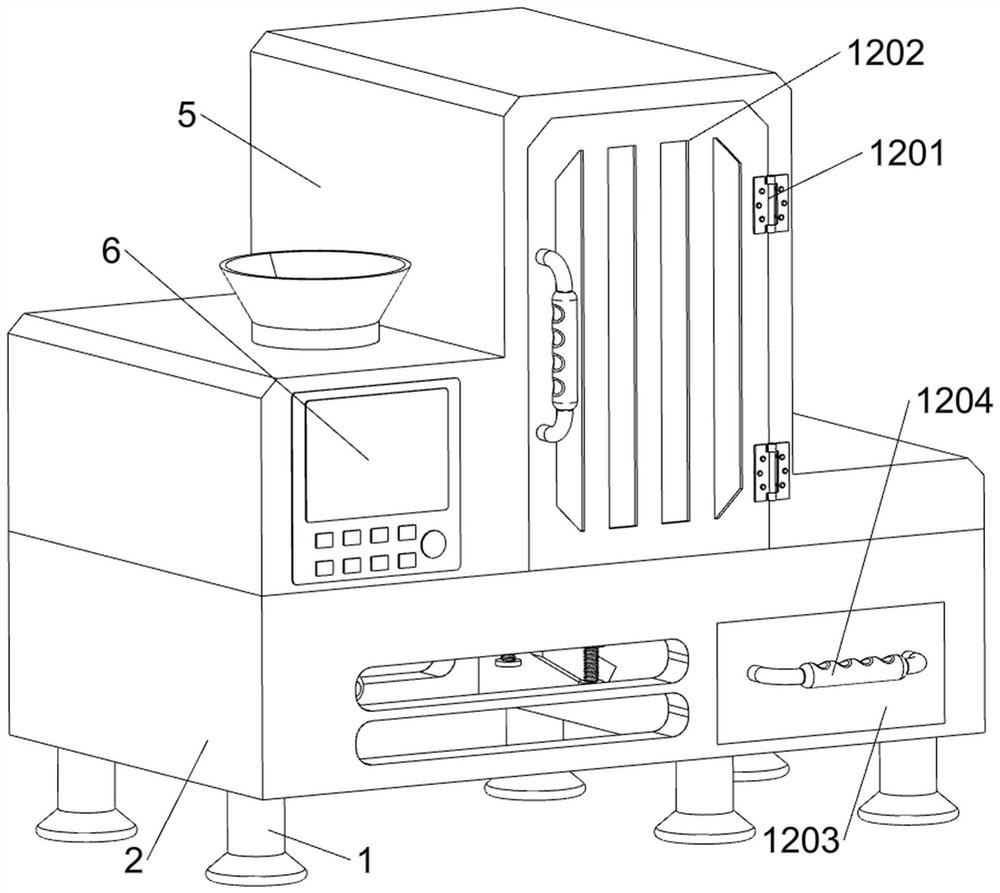
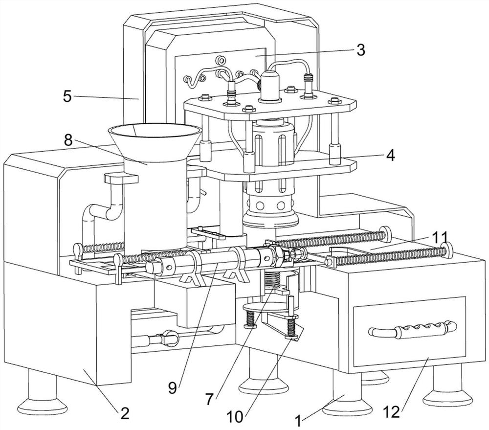
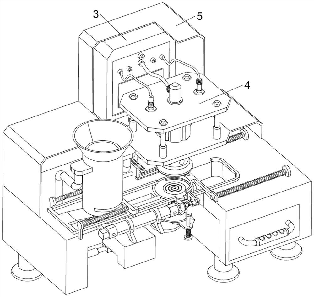
[0035] A kind of magnetic equipment for magnetic steel during the production of magnetic steel, such as figure 1 , figure 2 , image 3 , Figure 4 , Figure 5 , Image 6 with Figure 10 As shown, it includes a support column 1, a workbench 2, an electric control box 3, a magnetization module 4, a protective frame 5, a control panel 6, an ejection assembly 7, a discharge assembly 8 and a push assembly 9, and the workbench 2 There is a groove on the right front side of the top, three support columns 1 are provided on the front and rear sides of the bottom of the workbench 2, a protective frame 5 is provided on the top of the workbench 2, an electric control box 3 is provided on the rear side of the top of the workbench 2, and the electric control box 3 Located on the rear side of the protective frame 5, the top and rear side of the workbench 2 is provided with a magnetization module 4, which is connected to the electric control box 3 through wires, and the magnetization mo...

Embodiment 2

[0041] On the basis of Example 1, such as figure 1 , Figure 5 , Figure 7 , Figure 8 , Figure 9 , Figure 11 , Figure 12 , Figure 13 , Figure 14 with Figure 15 As shown, a positioning assembly 10 is also included, and the positioning assembly 10 includes a telescopic rod 1001, a pulley 1002, a third spring 1003, a second guide rod 1004, a wedge block 1005, a positioning block 1006 and a fourth spring 1007, and the push rod 903 The right side of the lower part is provided with a telescopic rod 1001, the right side of the telescopic rod 1001 is slidingly provided with a pulley 1002, a third spring 1003 is provided between the pulley 1002 and the telescopic rod 1001, and a second guide rod 1004 is provided on the front and rear sides of the bottom of the guide ring 701 The second guide bar 1004 is slidingly provided with a wedge block 1005, the pulley 1002 is combined with the wedge block 1005, the inside of the guide ring 701 is slidingly provided with a positioni...


PUM


Abstract

The invention relates to magnetization equipment, in particular to magnetic steel magnetization equipment for magnetic steel production. The invention aims to provide magnetic steel magnetization equipment for magnetic steel production, which can automatically push materials and has a discharging function. According to the technical scheme, the magnetic steel magnetization equipment for magnetic steel production comprises a workbench which is provided with a groove formed in one side of the top thereof; six supporting columns which are symmetrically connected to the two sides of the bottom of the workbench; a protective frame which is connected to the top of the workbench; an electric control box which is mounted on one side of the top of the workbench, and is located on one side of the interior of the protective frame; and a magnetizing module which is mounted on one side of the top of the workbench. When a piston rod of an air cylinder extends, a material pushing rod is driven to push magnetic steel rightwards, and thus, an automatic material pushing effect is achieved. Under the effect of a limiting block, the material pushing rod can accurately push the magnetic steel to an ejection plate. Meanwhile, the stability of the magnetic steel is improved through the limiting block.

Description

technical field [0001] The invention relates to a magnetizing device, in particular to a magnetizing device for magnet steel during magnet steel production. Background technique [0002] Magnetic steel, also known as AlNiCo alloy, is composed of several hard and strong metals. It is a natural magnet, and it is also the most widely used permanent magnet material. [0003] At present, in the magnetic steel production enterprises, most of the traditional magnetic steel magnetizing equipment manually place the magnetic steel on the magnetizing block. At the same time, it does not have the function of unloading. The steel is removed and collected, and such a cycle, the magnetization speed of the magnet steel is slow, the magnetization efficiency is not high, and there are problems such as being unable to meet the demand for magnet steel in the current market. [0004] To sum up, it is necessary to design a magnetic steel magnetizing equipment that can automatically push material...

Claims


Application Information

Patent Timeline
Patent Type & Authority Applications(China)
IPC IPC(8): G01L1/00B65G47/82B65G47/19
CPCG01L1/00B65G47/82B65G47/19Y02P10/20
Inventor 朱明王寰宇陆柄森
Owner JIANGXI YG MAGNET CO LTD
Why Eureka
Try Eureka