Monkey wrench assembly
A technology of adjustable wrench and components, which is applied in the direction of wrench, hand-held tools, wrench, etc., to achieve the effect of improving work efficiency
- Summary
- Abstract
- Description
- Claims
- Application Information
AI Technical Summary
Problems solved by technology
Method used
Image
Examples
Embodiment 1
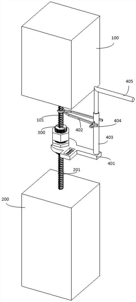
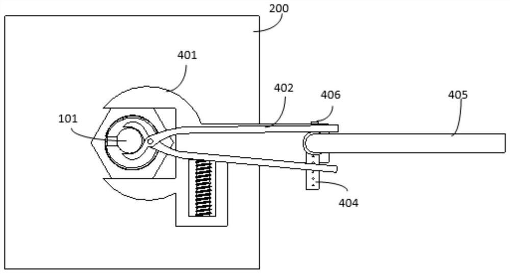
[0032] refer to figure 1 As shown in the figure, an adjustable wrench assembly is shown, and the adjustable wrench assembly includes: a wrench 401 , a clamping piece 402 , a vertical rod 403 and a rocker 405 . The wrench 401 is used to realize the screwing operation of the nut to be operated. The clamping piece 402 is used to assist in the memory and auxiliary positioning of the adjustable wrench assembly. The upright bar 403 is a fixed arm of the wrench 401 and the clamping piece 402 . The rocker 405 is used to realize the screwing operation of the wrench 401 .
[0033] Preferably, the end of the wrench 401 is rigidly connected to the bottom end of the upright rod 403 , and the upright rod 403 is perpendicular to the rotating surface of the wrench 401 . Thereby can drive upright rod 403 memory rotation by more, realize the rotation to wrench 401.
[0034] Further, the upright rod 403 is welded to the wrench 401 . Therefore, the stable connection between the vertical rod ...
Embodiment 2
[0042] refer to Figure 1 to Figure 3 As shown, on the basis of Embodiment 1, this embodiment discloses a usage example of an adjustable wrench assembly. Specifically, during the construction process of the beam-column joints of the assembled building, it is necessary to realize the connection of steel bars between prefabricated beams or prefabricated columns through sleeve locking parts. During the process of fastening the steel bars at both ends of the sleeve locking piece, it is necessary to use a wrench to twist the fastening nuts on the sleeve locking piece.
[0043] However, at the connection nodes of beams and columns, it is often impossible to use the traditional "one"-shaped wrench for work due to the position limitation between the beams and columns. Therefore, there is a need for a wrench assembly capable of avoiding the confined space and continuing the nut screwing operation.
[0044] The figure includes a first prefabricated part 100 and a second prefabricated pa...
Embodiment 3
[0050] refer to Figure 4 to Figure 6 . On the basis of Embodiment 2, the present invention also discloses a sleeve locking member 300 .
[0051] Preferably, the locking sleeve 301 is a sectional structure along the axial direction of the sleeve. Further, the locking sleeve 301 is not limited to split in half along the axial direction of the sleeve. For example, splitting can be done in half, equal-angle trisection or multi-division.
[0052] Preferably, when the locking sleeve 301 is divided into two sections along the axial direction of the sleeve, the locking sleeve 301 is internally divided into a first sleeve part 301a and a second sleeve part 301b.
[0053] Preferably, the outer wall of the locking sleeve 301 is provided with a wedge-shaped threaded portion. The fastening nut is sleeved on the outer side of the locking sleeve 301 and matched with the threaded portion. The first end reinforcing bar 101 and the second end reinforcing bar 201 are respectively sleeved i...
PUM
 Abstract
Description
Claims
Application Information
 - R&D
- Intellectual Property
- Life Sciences
- Materials
- Tech Scout
- Unparalleled Data Quality
- Higher Quality Content
- 60% Fewer Hallucinations
Browse by: Latest US Patents, China's latest patents, Technical Efficacy Thesaurus, Application Domain, Technology Topic, Popular Technical Reports.
© 2025 PatSnap. All rights reserved.Legal|Privacy policy|Modern Slavery Act Transparency Statement|Sitemap|About US| Contact US: help@patsnap.com


