
Rotary damper

A technology of rotary damper and damping oil, applied in shock absorbers, shock absorbers, liquid shock absorbers, etc., can solve the problems of small damping torque, many components, and time-consuming assembly.

Pending Publication Date: 2021-12-21
上海琦天汽车零部件有限公司
View PDF0 Cites 0 Cited by
  • Summary
  • Abstract
  • Description
  • Claims
  • Application Information

AI Technical Summary

Problems solved by technology

[0002] In the existing rotary damper, the oil passage gap for the damping oil is set on the surface of the rotating shaft. Since the surface of the rotating shaft is close to the shaft core, the moment arm of the damping force formed when the damping oil flows from the high-pressure oil chamber to the low-pressure oil chamber is short, resulting in the formation of The damping torque is small, resulting in a drop in damping force
In addition, the existing damping device has many components, time-consuming assembly, and high cost

Method used


Image

  • Rotary damper
  • Rotary damper
  • Rotary damper

Examples


Embodiment Construction

[0029] The embodiments of the present invention will be described in further detail below in conjunction with the accompanying drawings, but the present embodiments are not intended to limit the present invention, and any similar structures and similar changes of the present invention should be included in the protection scope of the present invention.

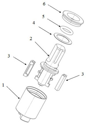
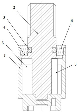
[0030] Such as Figure 1 to Figure 5 As shown, a rotary damper includes a cylinder 1 that can be filled with damping oil, an end cover 6, a sealing ring 5, a washer 4, and is located in the inner cavity of the cylinder 1 and rotates with the inner wall of the cylinder 1 to disturb the flow of the damping oil. The rotating shaft 2 and the two one-way valve plates 3, the upper end of the rotating shaft 2 is provided with a sealing ring 5 which is sealed with the inner wall of the cylinder body 1 to form a closed oil chamber.

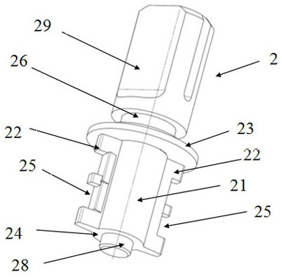
[0031] The rotating shaft 2 includes a shaft core 21 and two rotors 22 opposite to the shaft core 21. E...


PUM


Abstract

The invention discloses a rotary damper, and relates to the technical field of falling buffering of a washing machine cover plate or a toilet cover plate. The rotary damper solves the problem that an existing device is complex in structure and small in damping force. The rotary damper comprises a cylinder body, a rotating shaft and two one-way valve plates, wherein the cylinder body can be filled with damping oil, and the rotating shaft is located in an inner cavity of the cylinder body, is in running fit with the inner wall of the cylinder body and disturbs flowing of the damping oil. The rotary damper is characterized in that arc surfaces which are arranged in a left-and-right symmetry manner and are gradually changed in the radial direction are arranged on the wall surface of the inner cavity of the cylinder body and are located between two oil separation ribs. The rotating shaft comprises a shaft core and two rotor wings which are oppositely arranged relative to the shaft core. Each one-way valve plate sleeves the corresponding rotor wing of the rotating shaft and is in sliding fit with the inner wall of the cylinder body, oil passing gaps are formed by the valve plates and the gradual change type arc surfaces of the inner wall of the cylinder body, and the damping oil flows from a high-pressure oil chamber to a low-pressure oil chamber through the oil passing gaps so as to form the damping force. The rotary damper has the advantages of being simple in structure, large and stable in damping force, good in assembly and maintainability, low in cost and the like.

Description

technical field [0001] The invention relates to a rotary damper, in particular to a rotary damper for slowly lowering a washing machine cover or a toilet cover. Background technique [0002] In the existing rotary damper, the oil passage gap for the damping oil is set on the surface of the rotating shaft. Since the surface of the rotating shaft is close to the shaft core, the moment arm of the damping force formed when the damping oil flows from the high-pressure oil chamber to the low-pressure oil chamber is short, resulting in the formation of The damping torque is small, causing the damping force to drop. In addition, the existing damping device has many components, and the assembly is time-consuming and costly. Therefore, it needs to be further improved. Contents of the invention [0003] The purpose of the present invention is to provide a rotary damper, which has the advantages of simple structure, large and stable damping force, good assembly and maintainability, ...

Claims


Application Information

Patent Timeline
Patent Type & Authority Applications(China)
IPC IPC(8): F16F9/10F16F9/32F16F9/34F16F9/36F16F9/48
CPCF16F9/10F16F9/3207F16F9/3271F16F9/34F16F9/369F16F9/48
Inventor 马宇彪
Owner 上海琦天汽车零部件有限公司
Learn More