

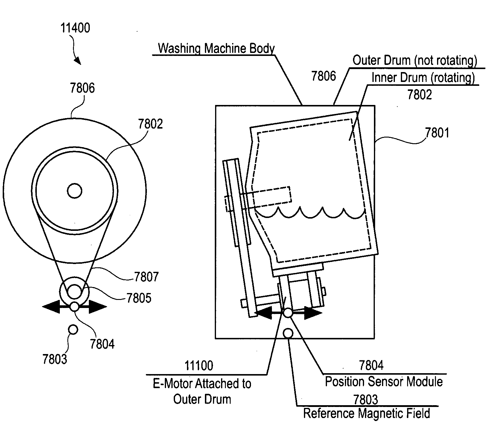
Position Sensor and Washing Machine
a technology of positioning sensor and washing machine, which is applied in the field of sensors, can solve the problems of inability to accurately and cheaply determine the accuracy and cheapness of the method, and the material may cover the optical marker, etc., and achieve the effect of accurate and cheap
- Summary
- Abstract
- Description
- Claims
- Application Information
AI Technical Summary
Benefits of technology
Problems solved by technology
Method used
Image

Examples
Embodiment Construction
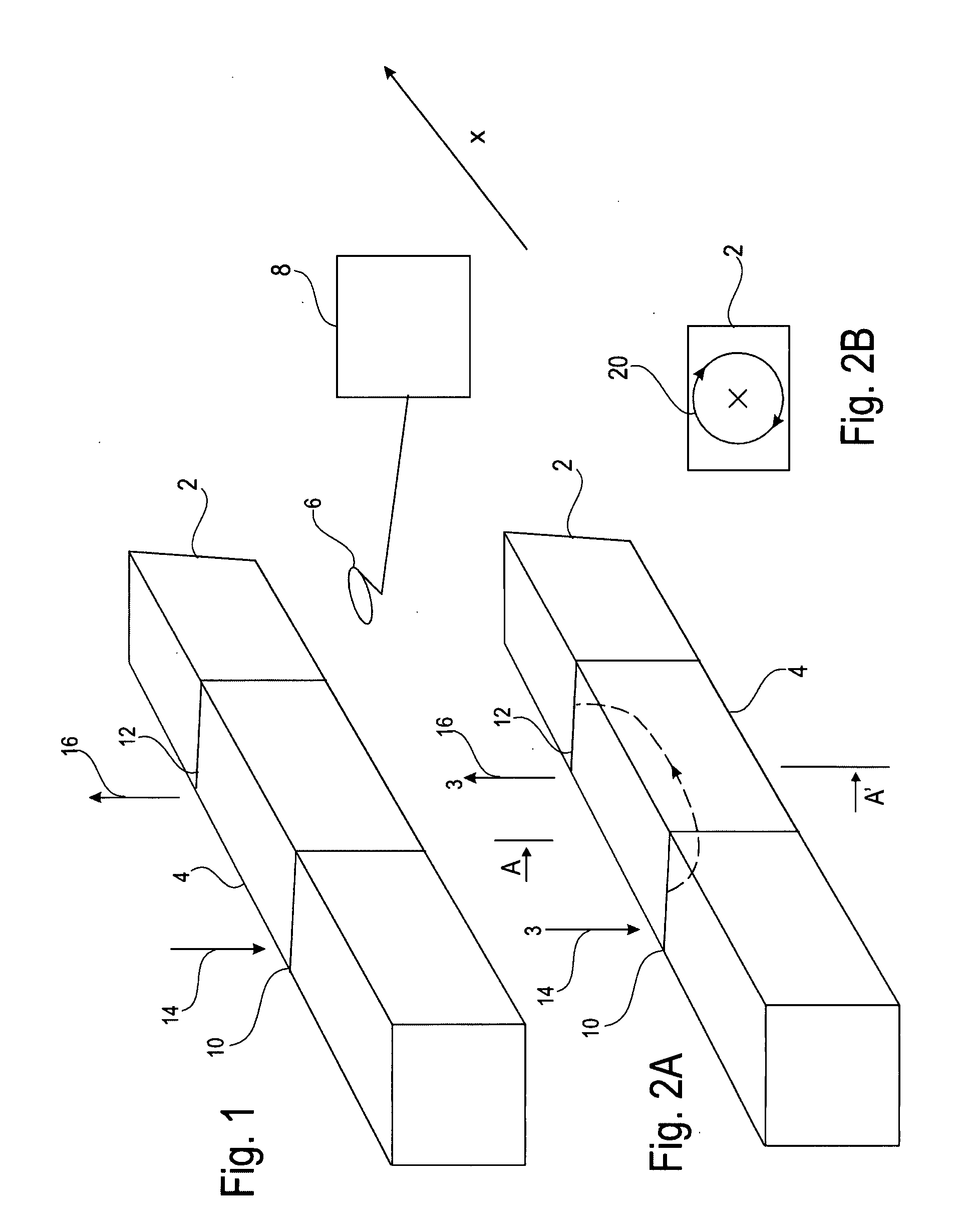
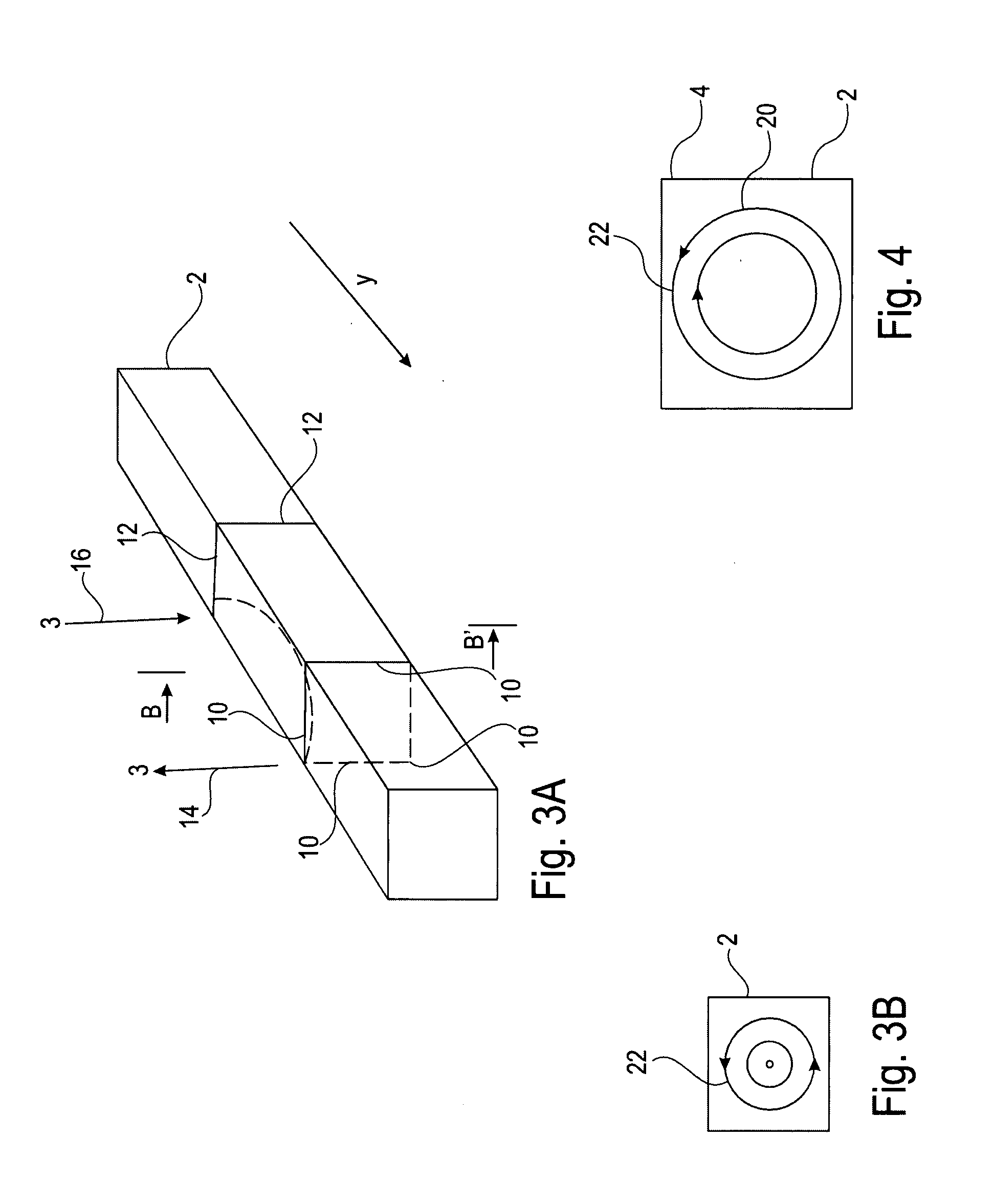
[0200]It is disclosed a sensor having a sensor element such as a shaft wherein the sensor element may be manufactured in accordance with the following manufacturing steps[0201]applying a first current pulse to the sensor element;[0202]wherein the first current pulse is applied such that there is a first current flow in a first direction along a longitudinal axis of the sensor element;[0203]wherein the first current pulse is such that the application of the current pulse generates a magnetically encoded region in the sensor element.
[0204]It is disclosed that a further second current pulse may be applied to the sensor element. The second current pulse may be applied such that there is a second current flow in a direction along the longitudinal axis of the sensor element.
[0205]It is disclosed that the directions of the first and second current pulses may be opposite to each other. Also, each of the first and second current pulses may have a raising edge and a falling edge. Preferably, ...
PUM
| Property | Measurement | Unit |
|---|---|---|
| Pressure | aaaaa | aaaaa |
| Magnetic field | aaaaa | aaaaa |
| Current | aaaaa | aaaaa |
Abstract
Description
Claims
Application Information