


Quick Research
Generate reliable direction feasibility study reports for your R&D in just a few steps.

Technical Q&A
Discover and master advanced knowledge NOW. Basics, ideas, possibilities, all at once.

Find Solutions
As an expert in R&D theories, this can generate solutions to your technical problems instantly.

Evaluate Feasibility
Analyze your overall solution with one click, know your potential R&D risks in advance.

Monitor Landscape
Get weekly tech updates, stay abreast of the latest tech innovations and key insights.
Magnifying glass detection jig and detection method
A technology for detection fixtures and detection methods, which is applied to measuring devices, material analysis through optical means, instruments, etc., can solve the problems of lower pass rate of magnifying glass, low detection efficiency, easy to miss the magnifying glass, etc., and achieve intuitive detection results , Speed up the detection speed, increase the effect of flexibility
- Summary
- Abstract
- Description
- Claims
- Application Information
AI Technical Summary
Problems solved by technology
Method used
Image

Examples
Embodiment 1
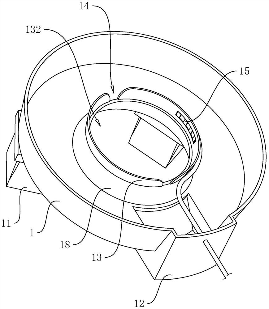
[0045] Present embodiment 1 discloses magnifying glass detection fixture, with reference to figure 1, including a jig body 1, which is provided with two supporting feet 11, and the jig body 1 is also provided with a placement groove 13 with an opening upward and for placing workpieces, and the inner wall of the placement groove 13 abuts against the side wall of the workpiece , the inner wall of the placement groove 13 is provided with an LED lamp 15 .
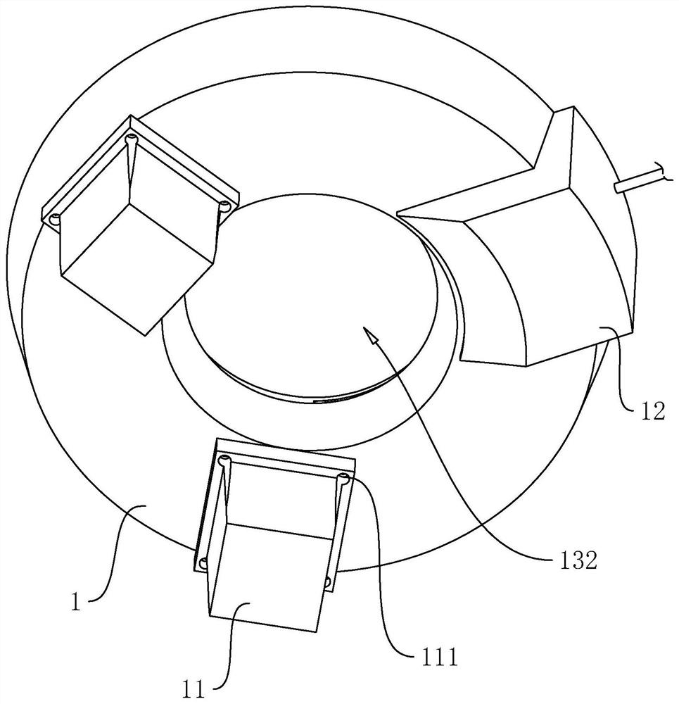
[0046] The jig body 1 is an arc-shaped groove, arranged horizontally, and an opening is arranged on the top surface. Two supporting feet 11 are provided on the outer wall of the bottom wall of the jig body 1 . to combine figure 2 , the supporting foot 11 is in the shape of a long column and is arranged vertically. A through hole 111 is disposed on the top of the supporting leg 11, and the through hole 111 is matched with a bolt. The supporting feet 11 are threadedly connected with the outer wall of the bottom wall of the j...
Embodiment 2
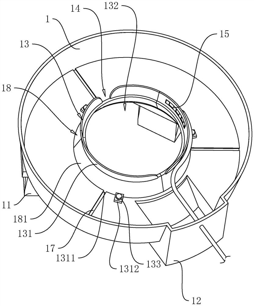
[0054] refer to image 3 The difference between this embodiment and Embodiment 1 is that the side wall of the placement groove 13 includes three side plates 131 . The side panels 131 are made of elastic material. The side plates 131 are in the shape of a long arc plate, and the plate surface is inclined relative to the bottom wall of the jig body 1 , and the two ends of the three side plates 131 in the length direction are connected end to end to form a placement slot 13 .
[0055] Likewise, the raised portion 18 includes three connecting plates 181 made of elastic material. The connecting plates 181 are in the shape of long arc plates, and the board surfaces are inclined. The three connecting plates 181 are connected end to end to form the raised portion 18 . The three connecting plates 181 correspond to the three side plates 131 one by one, and the top ends of the connecting plates 181 are fixedly connected to the bottom ends of the side plates 131 . An elastic component ...
Embodiment 3
[0060] refer to Figure 5 The difference between this embodiment and Embodiment 1 is that a light-receiving plate 16 for covering the placement groove 13 is provided on the bottom wall of the jig body 1 . The light receiving plate 16 includes a fixed part 161 and a movable part 162. The fixed part 161 is in the shape of a long plate. The movable part 162 is in the shape of an arc plate, and the edge of the movable part 162 is fixedly connected with the end of the fixed part 161 which is far away from the bottom wall of the fixture body 1 in the length direction. catch. The movable part 162 is perpendicular to the fixed part 161 .
[0061] to combine Image 6 A plurality of photoresistors 163 are arranged on the plate surface of the movable part 162 facing the placement groove 13 . The photoresistor 163 spreads over the board surface of the movable part 162 and is fixedly connected with the board surface of the movable part 162 . Reminisce Figure 5 , the photoresistor 16...
PUM
 Abstract
Description
Claims
Application Information
 - R&D Engineer
- R&D Manager
- IP Professional
- Industry Leading Data Capabilities
- Powerful AI technology
- Patent DNA Extraction
Browse by: Latest US Patents, China's latest patents, Technical Efficacy Thesaurus, Application Domain, Technology Topic, Popular Technical Reports.
© 2024 PatSnap. All rights reserved.Legal|Privacy policy|Modern Slavery Act Transparency Statement|Sitemap|About US| Contact US: help@patsnap.com