Method for correcting azimuth beam center of mechanical-sweeping radar based on servo rotating speed

A beam center and azimuth technology, applied in the field of radar data processing, can solve the problems affecting the azimuth angle measurement accuracy, affecting the azimuth beam center, system angle deviation, etc., to achieve the effect of improving the azimuth angle measurement accuracy and correcting the system angle deviation.

Pending Publication Date: 2021-12-21
中安锐达(北京)电子科技有限公司
View PDF0 Cites 0 Cited by
  • Summary
  • Abstract
  • Description
  • Claims
  • Application Information

AI Technical Summary

Problems solved by technology

[0005] In the formula, is the beam center; is the offset angle of the target relative to the beam center. The offset angle is calculated by the sum and difference ratio. The rotation of the antenna will introduce additional system angle deviation, which will affect the azimuth beam center, thereby affecting the accuracy of azimuth angle measurement.

Method used


Image

  • Method for correcting azimuth beam center of mechanical-sweeping radar based on servo rotating speed
  • Method for correcting azimuth beam center of mechanical-sweeping radar based on servo rotating speed
  • Method for correcting azimuth beam center of mechanical-sweeping radar based on servo rotating speed

Examples


Embodiment Construction

[0023] In order to make the purpose, technical solutions and advantages of the embodiments of the present invention clearer, the technical solutions in the embodiments of the present invention will be clearly and completely described below. Apparently, the described embodiments are some, but not all, embodiments of the present invention. Based on the embodiments of the present invention, all other embodiments obtained by persons of ordinary skill in the art without creative efforts fall within the protection scope of the present invention.

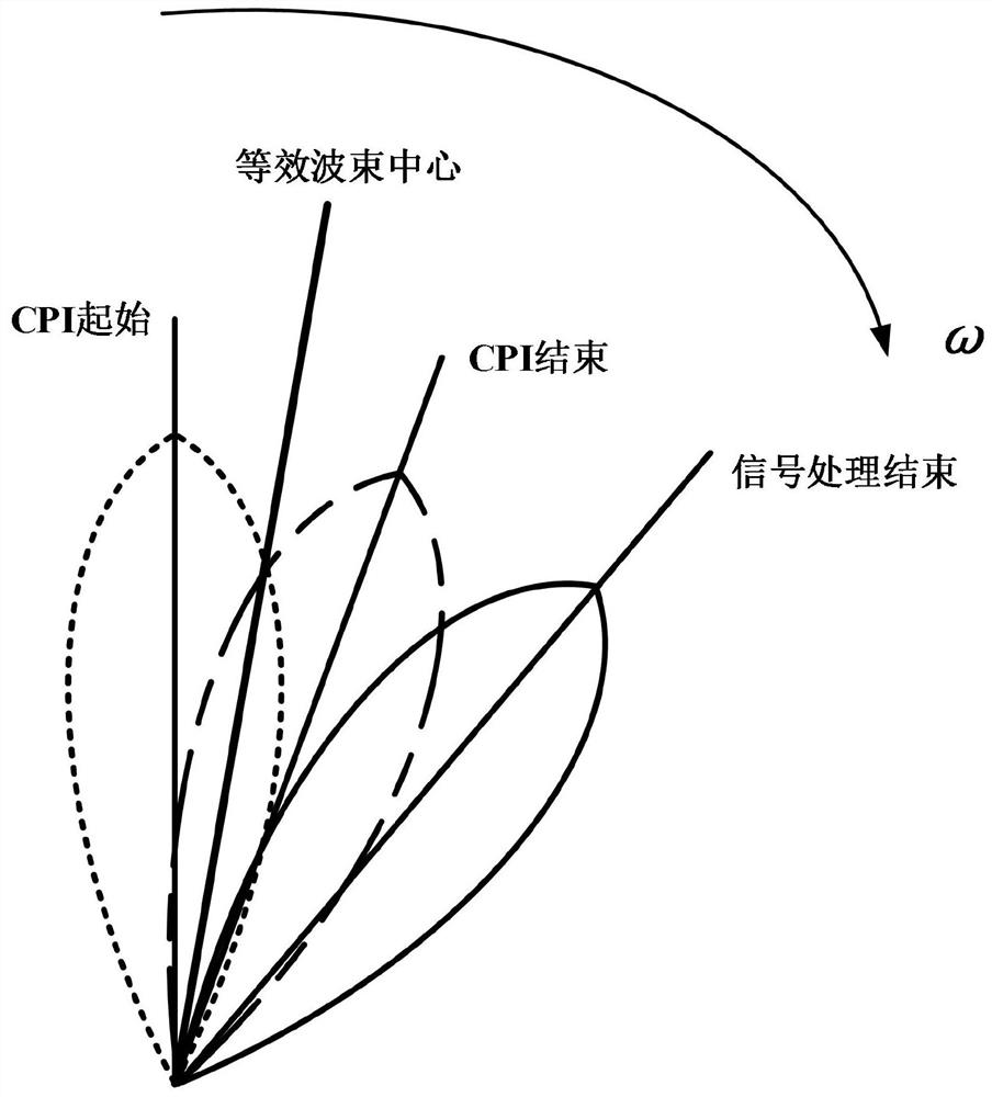
[0024] refer to figure 1 , the present invention will be further described in conjunction with embodiment.

[0025] A method for correcting the azimuth beam center of a machine-scanned radar based on a servo rotational speed, comprising the following steps:

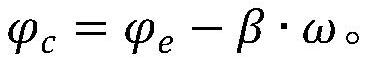
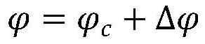
[0026] Suppose the corrected equivalent beam center is The angle after signal processing is The speed of the servo is Define the correction time of the equivalent azimuth beam...


PUM


Abstract

The invention relates to the technical field of radar data processing and particularly relates to a mechanical-sweeping radar azimuth beam center correction method based on servo rotating speed. The method comprises the following steps of assuming that a corrected equivalent beam center is an angle before signal processing as an angle after signal processing, and defining an azimuth beam center correction coefficient as alpha, according to angles of a servo before and after signal processing and based on the coherent processing interval and the signal processing time, an equivalent azimuth beam center is calculated, and the specific calculation method is that the equivalent beam center is obtained by weighting an angle of an initial servo of the coherent processing interval and an angle of a servo after signal processing is finished; and the azimuth correction weighting coefficient of the equivalent beam center is calculated based on the coherent processing interval and the signal processing time, so the system angle deviation introduced by the rotation of the antenna in the mechanical sweeping radar can be effectively corrected, and azimuth angle measurement precision is effectively improved.

Description

technical field [0001] The invention relates to the technical field of radar data processing, in particular to a method for correcting the azimuth beam center of a machine-scanned radar based on a servo rotational speed. Background technique [0002] The existing one-dimensional phased-array radar with azimuth machine-scanning and pitching-electrical-scanning systems generally adopts the method of sum-difference ratio-amplitude angle measurement in azimuth to improve the accuracy of angle measurement. However, during the scanning of the azimuth beam, the rotation of the antenna will cause the beam center to change, and the position of the target relative to the beam center will change, that is, within a coherent processing interval (Coherent Processing Interval, CPI), each pulse repeats The position of the target relative to the beam center within the interval (Pulse Repetition Interval, PRI) is different. [0003] For radars that use the sum-difference ratio to measure the...

Claims


Application Information

Patent Timeline
IPC IPC(8): G01S7/40G01S13/06
CPCG01S7/40G01S13/06
Inventor 陆晓明范延伟周仕祺童朝平彭文丽彭嘉宇彭学江杨瑞明郭云燕
Owner 中安锐达(北京)电子科技有限公司
Why Eureka
Try Eureka