
Zoom projection optical system

A projection optical system and focal length technology, applied in the field of optical systems, can solve the problem of different degrees of thermal defocus between the wide-angle end and the telephoto end, and achieve the effects of reducing light energy loss, high relative illumination, and low distortion

Pending Publication Date: 2021-12-21
HUNAN CHIOPT OPTICAL TECH
View PDF0 Cites 2 Cited by
  • Summary
  • Abstract
  • Description
  • Claims
  • Application Information

AI Technical Summary

Problems solved by technology

For this reason, the present invention proposes a zoom projection optical system for the problem of different degrees of thermal defocus at the wide-angle end and the telephoto end

Method used

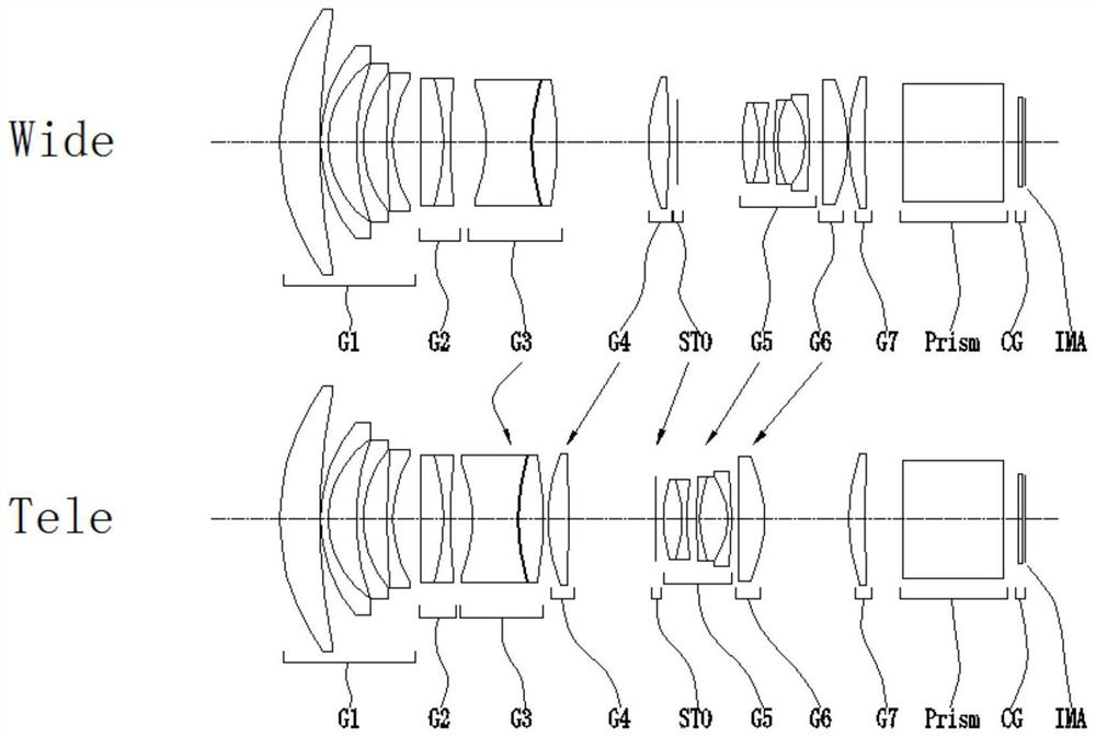
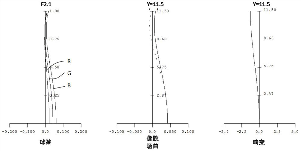
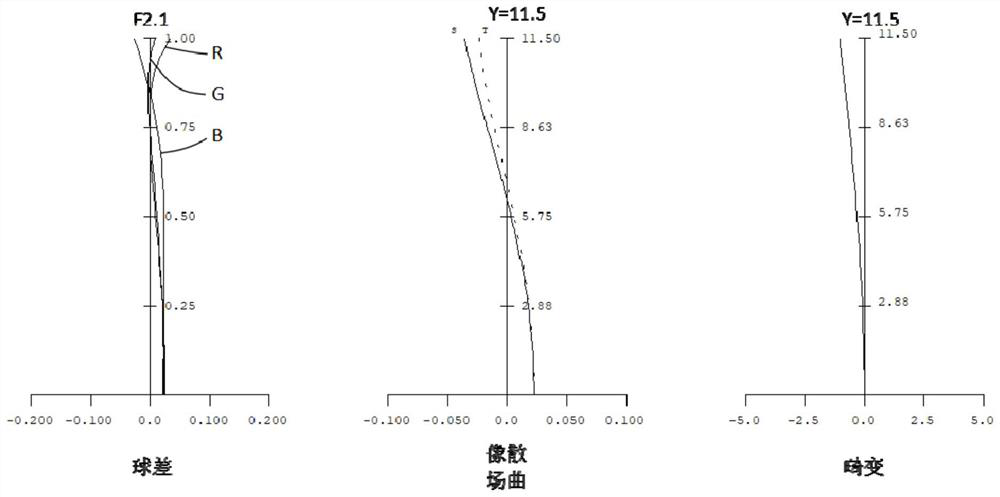

Image

  • Zoom projection optical system
  • Zoom projection optical system
  • Zoom projection optical system

Examples


Embodiment Construction

[0036] Embodiments of the present invention are described in detail below, examples of which are shown in the drawings, wherein the same or similar reference numerals designate the same or similar elements or elements having the same or similar functions throughout. The embodiments described below by referring to the figures are exemplary only for explaining the present invention and should not be construed as limiting the present invention.

[0037] In the description of the present invention, it should be understood that the orientation descriptions, such as up, down, front, back, left, right, etc. indicated orientations or positional relationships are based on the orientations or positional relationships shown in the drawings, and are only In order to facilitate the description of the present invention and simplify the description, it does not indicate or imply that the device or element referred to must have a specific orientation, be constructed and operated in a specific ...


PUM


Abstract

The invention discloses a zoom projection optical system, which comprises the following components which are sequentially arranged from an object side to an image side: a first lens group G1 which is fixed during zooming and has negative focal power; a second lens group G2 which can move along the direction of the optical axis, has positive focal power and is used for focusing different object distances; a third lens group G3 which can move along the optical axis direction and has positive focal power; a fourth lens group G4 which can move along the optical axis direction and has positive focal power; a diaphragm group STO which can move along the optical axis direction; a fifth lens group G5 which can move along the direction of the optical axis and has negative focal power; a sixth lens group G6 which can move along the direction of the optical axis and has positive focal power; a seventh lens group G7 which is fixed during zooming and has positive focal power; the zoom projection optical system has a constant Fno, and on the premise that the Fno is constant in the zoom process, the focal length is 17.68 mm to 28.28 mm, the zoom ratio is 1.6 *, the optical distortion is smaller than 1.3%, and the relative illumination is larger than 70%.

Description

technical field [0001] The invention relates to the field of optical systems, in particular to a zoom projection optical system. Background technique [0002] Currently, high lumens and high luminous flux projectors generally have thermal out-of-focus phenomena in the market. However, products with thermal out-of-focus need to focus repeatedly, which has a great impact on actual use. Especially for the zoom projection optical system, due to the inconsistent light energy loss between the wide-angle end and the telephoto end, there are cases where the degree of thermal defocus is different between the wide-angle end and the telephoto end. Commonly used solutions include mechanical structure heat dissipation compensation, optical design re-correction and compensation, etc. However, post-compensation means that the early design is invalid, and it takes more cost and time to correct and compensate. Contents of the invention [0003] The present invention aims to solve at least...

Claims


Application Information

Patent Timeline
Patent Type & Authority Applications(China)
IPC IPC(8): G02B15/163G02B15/14G02B13/00
CPCG02B15/1465G02B15/163G02B13/00
Inventor 焦建其白振
Owner HUNAN CHIOPT OPTICAL TECH
Learn More