
Slender pipe clamping chuck

A technology of slender tubes and chucks, which is applied in the field of tube material processing. It can solve the problems that the chucks cannot stably clamp slender tubes, and achieve the effects of avoiding processing quality, increasing the contact area, and reducing the length of the arm

Pending Publication Date: 2021-12-24
WUHAN ENG SCI & TECH RESINST
View PDF7 Cites 0 Cited by
  • Summary
  • Abstract
  • Description
  • Claims
  • Application Information

AI Technical Summary

Problems solved by technology

[0005] The purpose of the present invention is to overcome the above-mentioned technical deficiencies, propose a chuck for clamping a slender tube, and solve the technical problem that the chuck in the prior art cannot stably clamp the slender tube

Method used


Image

  • Slender pipe clamping chuck
  • Slender pipe clamping chuck
  • Slender pipe clamping chuck

Examples


Embodiment Construction

[0023] In order to make the object, technical solution and advantages of the present invention clearer, the present invention will be further described in detail below in conjunction with the accompanying drawings and embodiments. It should be understood that the specific embodiments described here are only used to explain the present invention, not to limit the present invention.

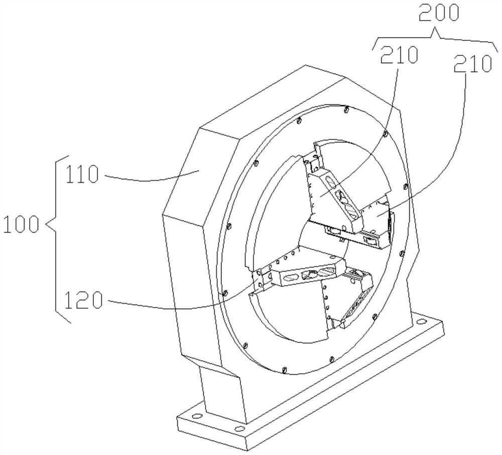
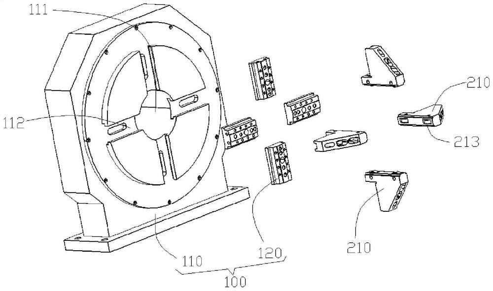
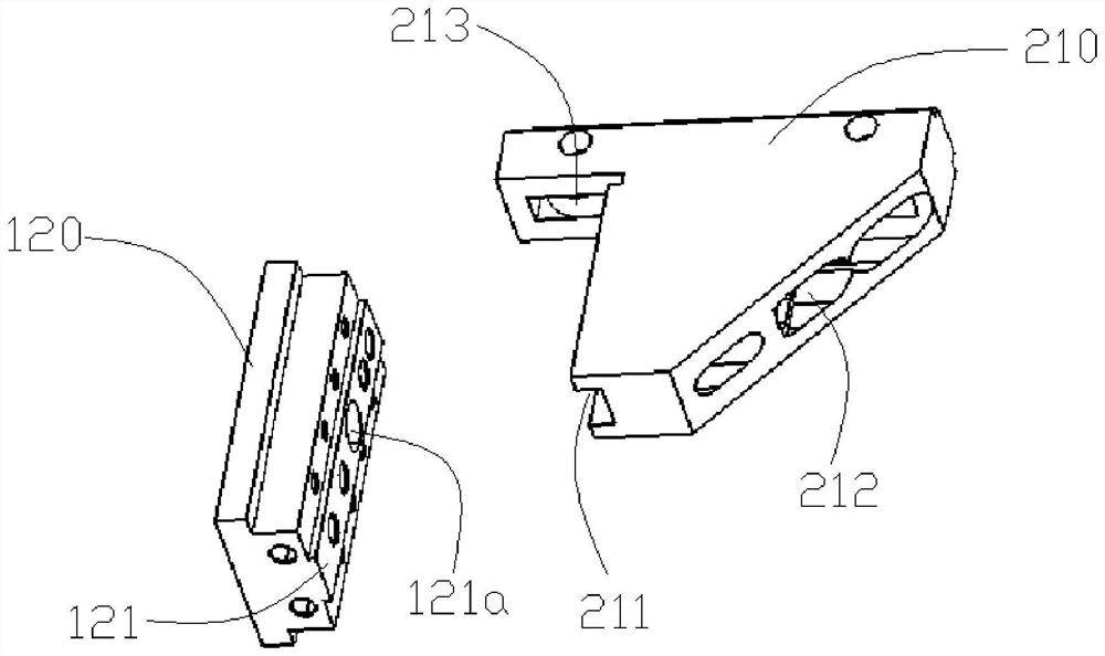
[0024] An embodiment of the present invention provides a chuck for clamping a slender tube, see figure 1 and figure 2 , which includes: a base 100 and a clamping piece 200 . The base 100 is provided with a guide hole 111 for the elongated tube to pass through, and the clamping member 200 includes a plurality of claws 210 surrounding the guide hole 111, so that the plurality of claws 210 can be distributed around the outer circumference of the elongated tube. It can be understood that the function of the plurality of jaws 210 is to clamp and fix the slender tube, so the relative position between ...


PUM


Abstract

The invention discloses a slender pipe clamping chuck which is characterized by comprising a base and a clamping piece, and a guide hole is formed in the base. The clamping piece comprises a plurality of clamping jaws surrounding the guide hole, at least part of the clamping jaws have the first state that the clamping jaws move relative to the base so as to be close to or away from the guide hole and the second state that the clamping jaws are fixed relative to the base, and each clamping jaw is provided with an extension part extending in the axial direction of the guide hole. The slender pipe penetrates through the guide hole, so that the clamping jaw can clamp the middle of the slender pipe, compared with clamping the end of the slender pipe, the length of a force arm of the slender pipe in the shaking process can be effectively reduced, and therefore the vibration amplitude of the slender pipe in the machining process is weakened. In addition, due to the fact that the contact area between the clamping jaws and the slender pipe is increased through the extension parts of the clamping jaws, the slender pipe can be clamped more stably through the clamping jaws, and the vibration amplitude of the slender pipe in the machining process is further reduced. And the problem that the machining quality is seriously influenced by too large amplitude of the slender pipe is avoided.

Description

technical field [0001] The invention relates to the field of pipe material processing, in particular to a clamping chuck for elongated pipes. Background technique [0002] In the field of pipe processing, the pipe is usually clamped and fixed by a chuck to facilitate processing of the pipe. [0003] For the specific structure of the chuck, please refer to the patent application number CN201780058861.7, which clamps and fixes the pipe with multiple claws, so that the processing equipment can process the pipe. Typically, such chucks are used to hold one end of the pipe while processing equipment processes the other end of the pipe. However, conventional chucks have significant drawbacks when clamping elongated tubes. On the one hand, the chuck clamps the end of the slender tube, so that the force arm of the clamped slender tube is too large, and it is easy to swing. On the other hand, due to the small diameter of the elongated tube, the contact area between the jaws and the...

Claims


Application Information

Patent Timeline
Patent Type & Authority Applications(China)
IPC IPC(8): B23B31/10B23B31/12
CPCB23B31/102B23B31/12
Inventor 陈和平江晟骆虎金彦孟丽王芬
Owner WUHAN ENG SCI & TECH RESINST
Learn More