
Efficient grinding device based on optical lens

An optical lens, high-efficiency technology, used in optical surface grinders, grinding drives, grinding/polishing safety devices, etc., can solve problems such as hidden safety hazards and cumbersome operations, and achieve the effect of efficient grinding and manpower saving

Pending Publication Date: 2021-12-24
上饶市桐宇光电科技有限公司
View PDF1 Cites 0 Cited by
  • Summary
  • Abstract
  • Description
  • Claims
  • Application Information

AI Technical Summary

Problems solved by technology

[0006] In order to overcome the disadvantages of the above-mentioned patent that manual loading is required, the operation is cumbersome, and when the optical lens is placed close to the grinding head, there is a certain potential safety hazard. The technical problem to be solved by the present invention is to provide a It is convenient for the operator to load the optical lens, the operation is relatively simple, and the grinding of the optical lens is relatively safe. The high-efficiency grinding device based on the optical lens

Method used


Image

  • Efficient grinding device based on optical lens
  • Efficient grinding device based on optical lens
  • Efficient grinding device based on optical lens

Examples


Embodiment 1

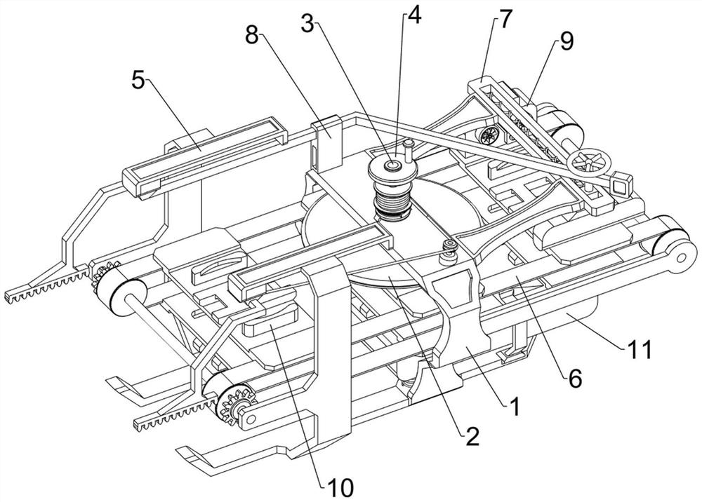
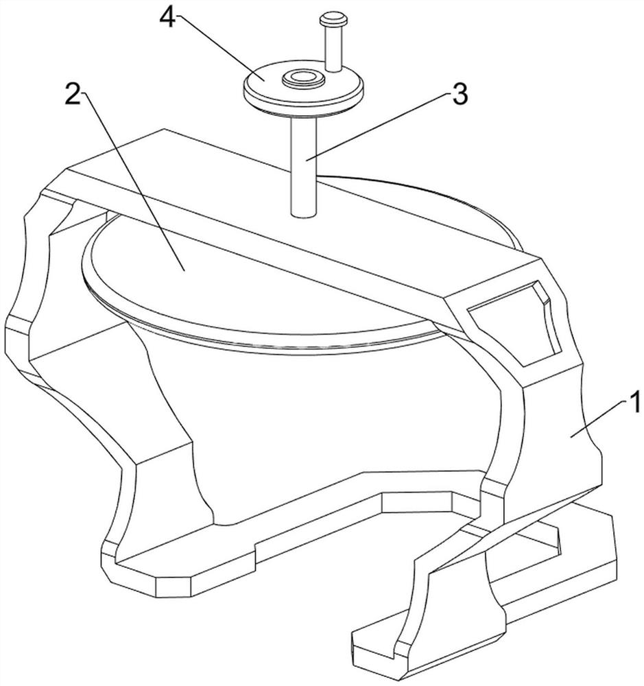
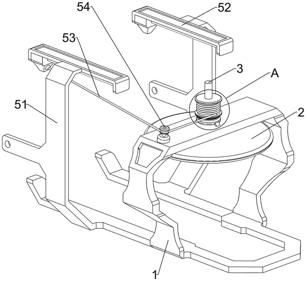
[0036] A high-efficiency grinding device based on optical lenses, such as figure 1 , figure 2 , image 3 , Figure 4 , Figure 5 , Image 6 , Figure 12 with Figure 13 As shown, it includes a connecting frame 1, a grinding disc 2, a rotating shaft 3, a rotating disk 4, a rotating mechanism 5, a conveying mechanism 6 and a clamping mechanism 10, and the middle position on the left side of the connecting frame 1 is rotatably connected with a rotating shaft 3. The bottom is welded with a grinding disc 2, the upper part of the rotating shaft 3 is riveted with a turntable 4, a rotating mechanism 5 capable of rotating is connected between the connecting frame 1 and the rotating shaft 3, and an optical lens is connected between the connecting frame 1 and the rotating mechanism 5. As for the conveying mechanism 6, a clamping mechanism 10 is connected to the conveying mechanism 6 to facilitate positioning of the optical lens.

[0037]Swivel mechanism 5 comprises connecting pla...

Embodiment 2

[0042] On the basis of Example 1, such as figure 1 , Figure 7 , Figure 8 , Figure 9 , Figure 10 with Figure 11 Shown, also comprise wiping mechanism 7, and wiping mechanism 7 comprises support plate 71, guide rail 72, slide bar 73 and sponge wipe 74, and two support plates 71 are welded symmetrically on the front and rear sides of connecting frame 1 top right side, two Be connected with the guide rail 72 that can be used for sliding guide between the right side of block support plate 71, the inboard sliding type of guide rail 72 is provided with slide bar 73, and the bottom of slide bar 73 is detachably installed with the sponge wipe 74 that can be used for wiping.

[0043] Also includes a power mechanism 8, the power mechanism 8 includes a second connecting rod 81, a fixed block 82 and a first spring 83, the rear side of the connecting frame 1 top is connected with a fixed block 82 by means of bolt connection, the top of the fixed block 82 The sliding type is connec...

Embodiment 3

[0047] On the basis of Example 2, such as figure 1 , Figure 14 with Figure 15 As shown, a receiving mechanism 11 is also included, and the receiving mechanism 11 includes a third spring 111, a charging frame 112 and a wedge block 113, and the inner bottom of the connecting frame 1 is connected with a charging frame 112 through a plurality of third springs 111 Wedge blocks 113 are symmetrically welded on the front and back sides of the right side of the connecting frame 1 , and the two wedge blocks 113 are in contact with the elastic splint 101 .

[0048] When the operator needs to collect the optical lenses that have been wiped, the optical lenses can be transported to the charging frame 112 under the transmission of the flat belt 66, and when the elastic splint 101 contacts and cooperates with the wedge block 113, it can be pushed Elastic splint 101 slides up and makes optical lens break away from groove 102, and second spring 103 shrinks thereupon, and optical lens falls...


PUM


Abstract

The invention relates to an efficient grinding device, in particular to an efficient grinding device based on an optical lens. According to the efficient grinding device based on the optical lens, an operator can conveniently feed the optical lens, operation is easy, and grinding of the optical lens is relatively safe. The efficient grinding device based on the optical lenses comprises a connecting frame, a grinding disc, a rotating shaft, a rotating disc and the like, wherein the rotating shaft is rotationally connected to the middle of the left side of the upper portion of the connecting frame, the grinding disc used for grinding is connected to the bottom of the rotating shaft, and the rotating disc is connected to the upper portion of the rotating shaft. The optical lens can be clamped and limited through the clamping effect of grooves in elastic clamping plates, so that displacement of the optical lens during grinding is avoided. Pistons on rodless air cylinders move left and right, a pull rope can be driven to be wound or loosened, and the optical lens is automatically fed through the transmission effect of flat belts; and under the reset action of a volute spiral spring, the grinding disc can be driven to rotate to quickly grind the optical lens.

Description

technical field [0001] The invention relates to a high-efficiency grinding device, in particular to a high-efficiency grinding device based on optical lenses. Background technique [0002] Since the optical lens is easy to leave some raised impurities on the surface when it is finished, it is generally necessary for the staff to hold the fine sandpaper to repeatedly polish the surface of the optical lens, then wipe the polished optical lens, and then store it. [0003] After searching, the patent publication number is: CN208913754U patent, which discloses a polishing device for optical lens processing, including a base, on which a first telescopic mechanism and an operating table are arranged, and the output end of the first telescopic mechanism is connected to a fixed plate. One end of the fixed plate is provided with a motor, the output end of the motor is connected with the rotating shaft, the lower end of the rotating shaft is threadedly connected with a grinding mechani...

Claims


Application Information

Patent Timeline
IPC IPC(8): B24B13/00B24B13/005B24B41/00B24B47/12B24B55/06B24B55/12
CPCB24B13/0018B24B13/0031B24B13/005B24B47/12B24B55/06B24B55/12B24B41/005Y02P70/10
Inventor 徐雁
Owner 上饶市桐宇光电科技有限公司
Learn More