High-efficiency package printing method

A packaging printing, high-efficiency technology, applied in the direction of printing, printing machines, rotary printing machines, etc., can solve the problems of inability to adjust the adjustment of the guide height, reduce efficiency, etc., and achieve the effect of improving efficiency

Inactive Publication Date: 2021-12-24
GUANGDONG MECHANICAL & ELECTRICAL COLLEGE
View PDF1 Cites 0 Cited by
  • Summary
  • Abstract
  • Description
  • Claims
  • Application Information

AI Technical Summary

Problems solved by technology

[0004] However, when the existing printing equipment guides and positions the printed products, it cannot adjust the guide height according to the needs of various products, which reduces the efficiency of subsequent printing of various packaging products, so a high-efficiency Packaging printing method and printing device, to solve the problems raised in the above-mentioned background technology

Method used


Image

  • High-efficiency package printing method
  • High-efficiency package printing method
  • High-efficiency package printing method

Examples


Embodiment 1

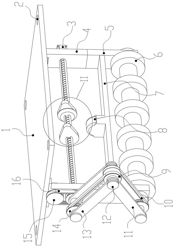
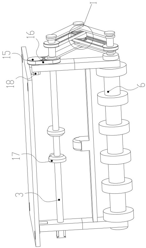
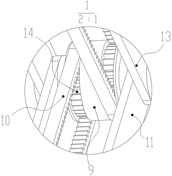
[0044] like Figure 1-9 As shown, it is the first embodiment of the present invention: a high-efficiency packaging printing device, including a mounting support plate 1, a threaded hole 2, an adjustment mechanism 3, a supporting side plate 4, a supporting bottom plate 5, a positioning connecting roller 6, an installation Bracket 7, limit block 8, double pulley 9, first installation connecting plate 11, limit insertion shaft 12, second installation connecting plate 13, toothed pulley 14, transmission pulley 15, second toothed belt 16, positioning Mechanism 17, connecting motor 18 and spring clamping shaft 19,

[0045] The upper end surface of the installation support plate 1 is evenly and equidistantly provided with four sets of threaded holes 2 for positioning, and the lower end surface of the installation support plate 1 is symmetrically fixedly connected with the support side plate 4 for positioning, and is located on the side of the support side plate 4. The side end surfa...

Embodiment 2

[0050] On the basis of Example 1, such as Figure 10 As shown, the connecting wheel shaft 171 is arranged in a circular shape, and rounded corners are provided on the sides of the connecting wheel shaft 171 for limiting positions.

[0051] When this embodiment is in use, if the user needs to always adjust the height of the device to guide the printed product, the user can move the two sets of positioning mechanisms 17 closer by performing the above steps, and the connecting wheel shaft 171 arranged in a circle can pass through the connection. The angle 173 presses the limit block 8 to the outside, and the closer the two sets of positioning mechanisms 17 are, the higher the displacement height of the positioning connecting roller 6 is pressed to the outside, which improves the conveying efficiency and adaptability of the device.

[0052] Utilize the equipment of embodiment 1 and embodiment 2 to implement efficient package printing process, its steps are as follows:

[0053] S1...


PUM


Abstract

The invention discloses a high-efficiency package printing method. The method is characterized by comprising the following steps: S1, firstly, a device is located at a proper region through an external connecting piece so that subsequent rapid guiding operation of a printed product can be facilitated, and the positioning and mounting stability of the device is improved; and S2, when the guiding operation is conducted on the printed product, a user can start a connecting motor (18) through an external control mechanism at the moment, the connecting motor (18) can drive a driving belt pulley (15) to rotate, when the driving belt pulley (15) rotates, an adjusting mechanism (3) can be driven to rotate through a second tooth-shaped belt (16), and when the adjusting mechanism (3) rotates, the adjusting mechanism (3) can drive a tooth-shaped belt pulley (14) at the front portion to rotate.

Description

technical field [0001] The invention relates to the technical field of printing equipment, in particular to a high-efficiency packaging printing method. Background technique [0002] Printing is the process of engraving text and other originals through plate making, ink application, and pressure, so that the paint is transferred to the surface of paper and other materials, so that users can batch produce a large number of patterns and text, and improve printing efficiency. [0003] According to an invention patent of Chinese Patent No. CN201910033236.8, it discloses that the present invention relates to the technical field of packaging bag printing, and discloses a packaging bag printing device with high printing efficiency, including a support seat, the top of which is A motor is fixedly installed, the top of the support base is fixedly equipped with a motor protection cover outside the motor, the output shaft of the motor is fixedly installed with a driving wheel on the ri...

Claims


Application Information

Patent Timeline
Patent Type & Authority Applications(China)
IPC IPC(8): B41F17/00B41F21/00
CPCB41F17/00B41F21/00
Inventor 何冰强
Owner GUANGDONG MECHANICAL & ELECTRICAL COLLEGE
Why Eureka
Try Eureka