A printing conveying device for the processing of steel plates on the side of the intelligent robot arm

An intelligent robot and conveying device technology, applied in printing, stamping and other directions, can solve the problems of incapable of horizontal and vertical cross conveying, falling of side steel plates, poor flexibility of side steel plates, etc., to improve conveying efficiency, improve work efficiency, and position precise effect

Active Publication Date: 2020-11-06
广西盛隆钢铁材料研究院有限公司
View PDF4 Cites 0 Cited by
  • Summary
  • Abstract
  • Description
  • Claims
  • Application Information

AI Technical Summary

Problems solved by technology

[0004] The purpose of the present invention is to solve the problem that the distance between the conveying device and the printing machine is relatively long when the opposite side steel plate is being processed, and after the conveying device transports the side steel plate to the printing machine, the side steel plate can only be unloaded and put back into the printing machine. Printing on the printing machine, this process is too cumbersome and time-consuming, and the conveying device is not stable and reliable when conveying the side steel plate. Cross-conveying, and the efficiency of printing on the opposite side of the printing machine is slow, the printing quality is poor, and the printing machine is easily damaged after long-term use, and it is inconvenient for people to repair and maintain the conveying device. Printing conveying device for steel plate processing on the side of the robot arm

Method used


Image

  • A printing conveying device for the processing of steel plates on the side of the intelligent robot arm
  • A printing conveying device for the processing of steel plates on the side of the intelligent robot arm
  • A printing conveying device for the processing of steel plates on the side of the intelligent robot arm

Examples


Embodiment Construction

[0044] The technical solutions of the present invention will be clearly and completely described below in conjunction with the embodiments. Apparently, the described embodiments are only some of the embodiments of the present invention, not all of them. Based on the embodiments of the present invention, all other embodiments obtained by persons of ordinary skill in the art without creative efforts fall within the protection scope of the present invention.

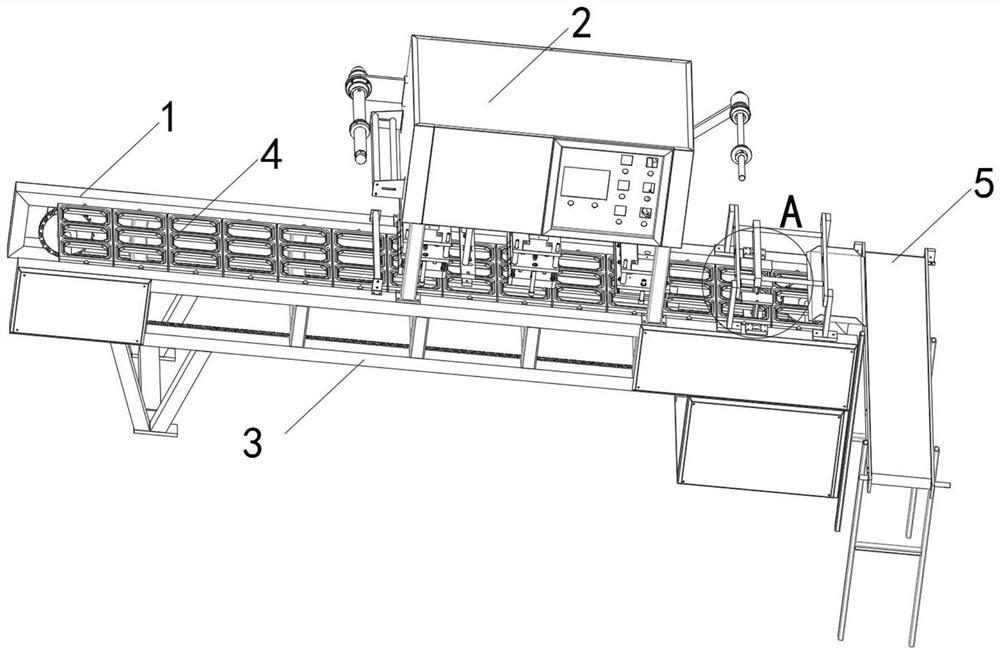
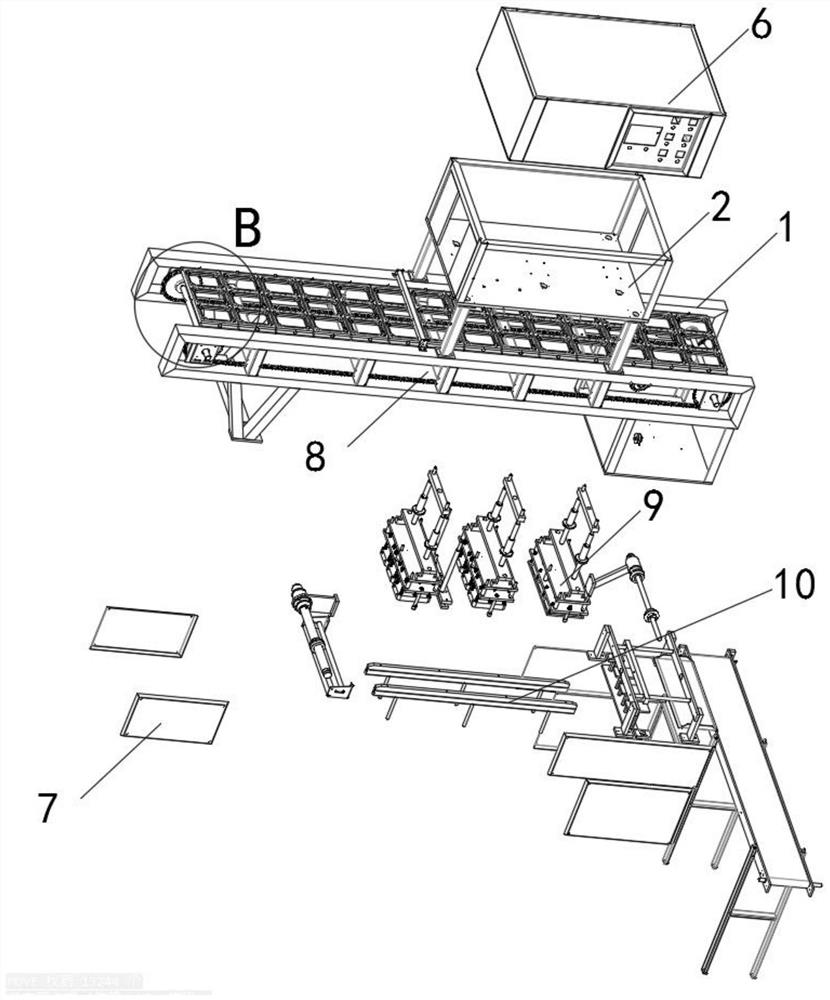
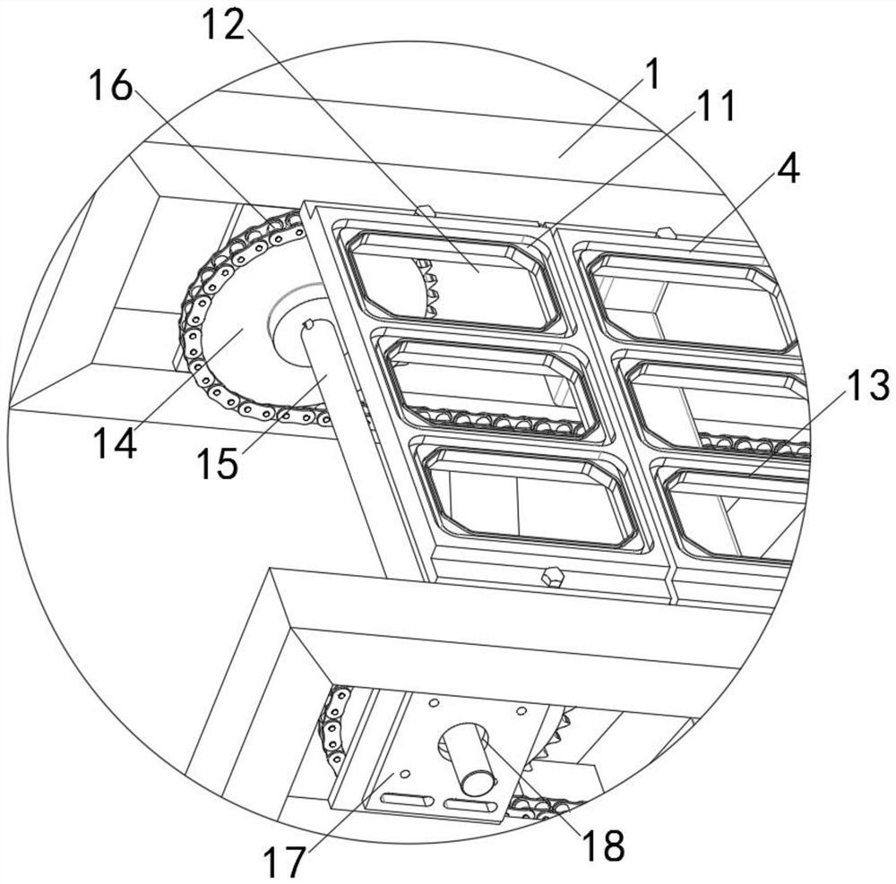
[0045] see Figure 1-10 As shown, a printing conveying device used for the processing of steel plates on the side of the intelligent robot arm, including the first conveying tray 1, the loading box 2, the side support frame 3, the plate loading frame 4 and the rear delivery platform 5, the first conveying tray 1 Two side support frames 3 are arranged in parallel at both ends, several loading frames 4 are placed side by side between the two side support frames 3, and an assembly box 2 is arranged above the middle part of the...


PUM


Abstract

The invention discloses a printing conveying device for intelligent robot arm side steel plate machining. The printing conveying device comprises a first conveying disc, a connecting box, side supporting frames, plate containing frames and a backward conveying table. The two side supporting frames are arranged at the two ends of the first conveying disc in parallel, and a plurality of plate containing frames are placed between the two side supporting frames. The connecting box is arranged above the middle of the first conveying disc, and the backward conveying table is vertically arranged at one end of the first conveying disc. Three printing tables are arranged at the bottom of the connecting box at equal intervals side by side. The printing conveying device has the beneficial effects that in cooperation with the three printing tables arranged at the bottom of the connecting box at equal intervals, side steel plates mounted in the three plate containing frames are synchronously printed, and the printing efficiency of the device on the side steel plates is improved; the device works in the manner of carrying out conveying and printing at the same time, and the overall work efficiency of the device is improved; and the device is convenient to operate, firm, durable and suitable for use and popularization, and has good social benefits and economic benefits.

Description

technical field [0001] The invention relates to a printing conveying device, in particular to a printing conveying device used for processing steel plates on the arm side of an intelligent robot, and belongs to the technical field of printing conveying devices. Background technique [0002] The side steel plate is indispensable on the intelligent robot arm. The side steel plate is equivalent to the "skin" on the robot arm, which can protect the circuit inside the arm. When the side steel plate is processed, a conveying device is needed to transport the side steel plate to the printing machine. The surface wall of the side steel plate is punched and printed, so that when the side steel plate is put into use, it is beneficial for people to identify the model, brand and other information of the side steel plate. [0003] At present, when the opposite side steel plate is processed, the distance between the conveying device and the printing machine is relatively long, and after t...

Claims


Application Information

Patent Timeline
Patent Type & Authority Patents(China)
IPC IPC(8): B41K3/04B41K3/50B41K3/64
Inventor 明园园
Owner 广西盛隆钢铁材料研究院有限公司
Why Eureka
Try Eureka