A kind of ampoule bottle printing device and using method thereof

An ampoule bottle and printing technology, which is applied to general parts of printing machinery, printing, printing machines, etc., can solve the problems of being easily scratched, stained with dust, unclear fonts, and unclear printing, etc. Printing processing efficiency, the effect of easy promotion and application

Active Publication Date: 2020-10-13
PUYANG LUMENG GLASS
View PDF15 Cites 0 Cited by
  • Summary
  • Abstract
  • Description
  • Claims
  • Application Information

AI Technical Summary

Problems solved by technology

[0003] Most of the current printing devices are conveying line type for printing, and the printing is not clear. The newly printed ink is easy to be scratched and stained with dust, resulting in unclear characters.

Method used


Image

  • A kind of ampoule bottle printing device and using method thereof
  • A kind of ampoule bottle printing device and using method thereof
  • A kind of ampoule bottle printing device and using method thereof

Examples


Embodiment 1

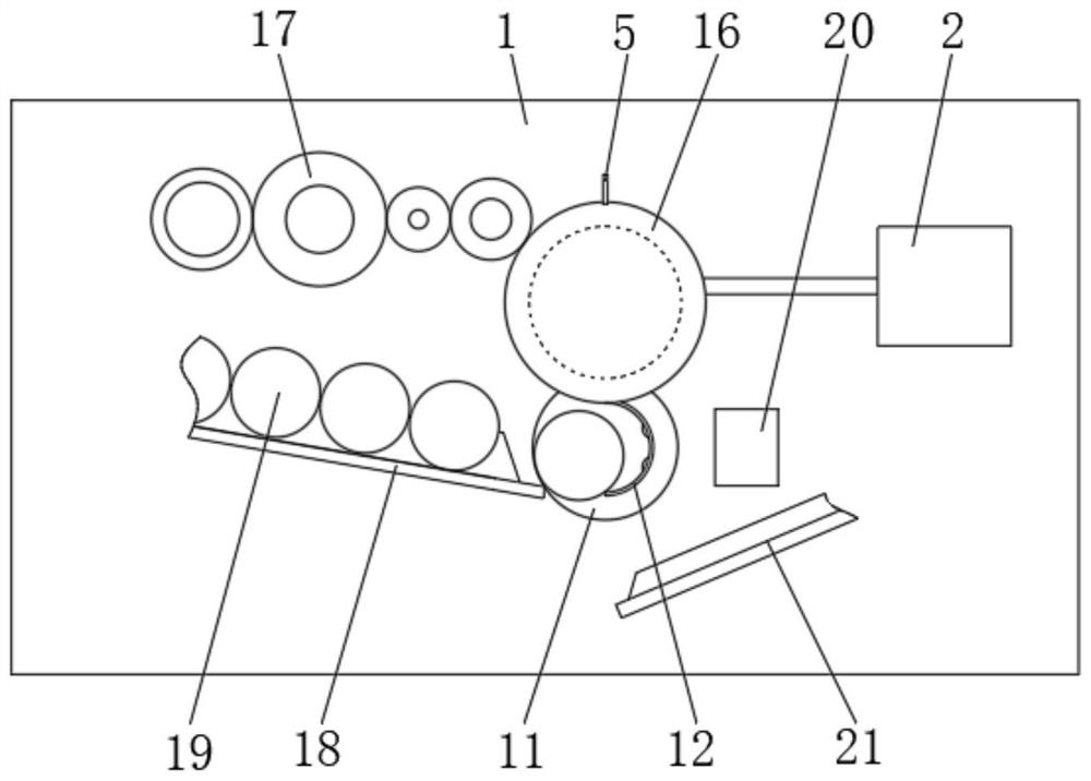
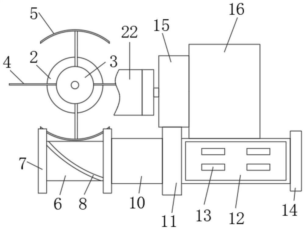
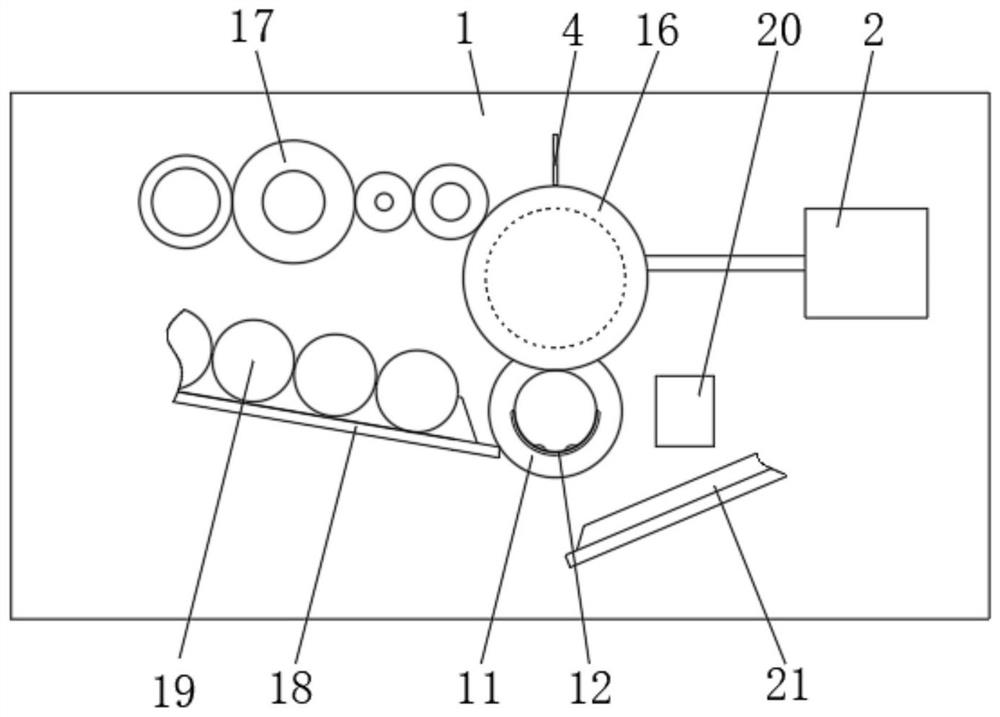
[0033] An ampoule bottle printing device, please refer to Figure 1 to Figure 5 , comprising: a fixed plate 1, a printing rubber roller 16 arranged to rotate relative to the fixed plate 1, a feeding device for conveying ampoules 19, a semi-cylinder 12 for receiving ampoules 19, and a semi-cylinder 12 for driving intermittently The first rotating transmission mechanism, the drying device used to dry the handwriting of the printed ampoule 19, the semi-cylinder 12 is connected to the printing rubber roller 16 through the second transmission mechanism, and the feeding device and drying device are set on the fixed plate 1 on.

[0034] The first transmission mechanism includes a toggle body and a passive body, the toggle body is connected with a motor 2 for driving the toggle body to continuously rotate, the continuous rotation of the toggle body can drive the passive body to rotate intermittently, and the passive body is directly or indirectly connected Half cylinder 12.

[0035]...

Embodiment 2

[0051] In this embodiment, the second transmission mechanism includes an upper sprocket, a chain and a lower sprocket, the upper sprocket is coaxially fixedly connected to the printing rubber roller 16, and one side of the lower sprocket is directly or indirectly coaxially fixedly connected to the side plate 7 , the other side of the lower sprocket is fixedly connected with the semi-cylinder 12, and the upper sprocket and the lower sprocket are connected by a chain. The intermittent rotation of the lower sprocket can drive the intermittent rotation of the upper sprocket. Other structures and principles are the same as those in Embodiment 1, and will not be repeated here.

Embodiment 3

[0053] The second transmission mechanism adopts a belt drive, including an upper pulley, a belt and a lower pulley, the upper pulley is fixedly connected with the printing rubber roller 16 coaxially, one side of the lower pulley is directly or indirectly fixedly connected with the side plate 7, and the other of the lower pulley One side is fixedly connected with the semi-cylinder 12, and the upper pulley and the lower pulley are connected by a belt. Other structures and principles are the same as those in Embodiment 1 and will not be repeated here.


PUM


Abstract

The invention discloses an ampoule bottle letter printing device and a using method thereof, wherein the ampoule bottle letter printing device comprises a fixed plate, a letter printing rubber rollerrotatably arranged relative to the fixed plate, a feeding device for transferring an ampoule bottle, a semicircular cylinder for receiving the ampoule bottle, a first transmission mechanism for driving the semicircular cylinder to do intermittent rotation, and a drying device for drying the letter printed on the ampoule bottle, wherein the semicircular cylinder is connected with the letter printing rubber roller through a second transmission mechanism; and the feeding device and the drying device are arranged on the fixed plate. After a letter is printed on the ampoule bottle, the ampoule bottle has temporary stay under the action of the first transmission mechanism, and the drying device dry the letter, so that the letter on the surface of the ampoule bottle is rapidly dried, clearly visible and unlikely to rub out.

Description

technical field [0001] The invention relates to the technical field of printing, in particular to an ampoule bottle printing device and a use method. Background technique [0002] Ampoule bottle or vial is a kind of packaging container widely used in pharmaceutical packaging. The text information on the surface includes the name, capacity, production date, batch number, etc. of the drug. These information are related to the life safety of the user, and the ampoule printing machine is Important equipment for printing this information. [0003] Most of the current printing devices are conveying line type for printing, and the printing is not clear, and the ink that has just been printed is easy to be scratched and stained with dust, resulting in unclear characters. Contents of the invention [0004] In view of the above problems, the present invention provides an ampoule bottle printing device and its use method, which has an ingenious and reasonable structure and clear pri...

Claims


Application Information

Patent Timeline
Patent Type & Authority Patents(China)
IPC IPC(8): B41F17/18B41F23/04
CPCB41F17/18B41F23/04
Inventor 赵健张俊波曹玉峰陈升军高航
Owner PUYANG LUMENG GLASS
Why Eureka
Try Eureka