Telescopic vortex generator and propeller hub formed by same

A vortex generator and telescopic technology, applied in the direction of propeller, by generating vortices, aircraft parts, etc., can solve the problems of poor operability, poor adaptability, troublesome loading and unloading, etc., and achieve the effect of easy operation, good adaptability, and convenient loading and unloading.

Active Publication Date: 2021-12-24
LOW SPEED AERODYNAMIC INST OF CHINESE AERODYNAMIC RES & DEV CENT
View PDF6 Cites 0 Cited by
  • Summary
  • Abstract
  • Description
  • Claims
  • Application Information

AI Technical Summary

Problems solved by technology

[0006] In order to overcome the deficiencies of the prior art, the present invention provides a telescopic vortex generator and the propeller hub it constitutes, which solve the problems existing in the prior art such as troublesome loading and unloading, difficult adjustment, poor operability, and poor adaptability.

Method used


Image

  • Telescopic vortex generator and propeller hub formed by same
  • Telescopic vortex generator and propeller hub formed by same
  • Telescopic vortex generator and propeller hub formed by same

Examples


Embodiment 1

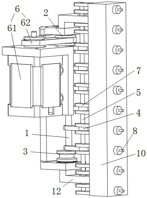
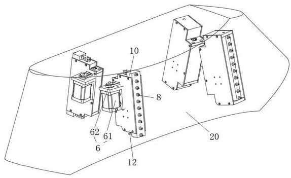
[0042] Such as Figure 1 to Figure 3 As shown, a telescopic vortex generator includes a pivot 1, a rotating connection block 4, a connecting rod 5, a driving device 6, a connecting rod seat 7, and a raised structure 8, and the pivot 1 and the driving device 6 connected, the driving device 6 is used to drive the pivot 1 to make a circular motion on a plane perpendicular to the axis centerline of the pivot 1, the pivot 1 is connected to the rotating connecting block 4, and the rotating connecting block 4 is connected to the rotating connecting block 4 The connecting rod 5 is rotationally connected, the connecting rod 5 is connected to the connecting rod base 7, the connecting rod base 7 is connected to the protruding structure 8, and the protruding structure 8 can pass through the middle of the propeller hub Shaft fairing.

[0043] During work, the driving device 6 drives the pivot 1 to make a circular motion on a plane perpendicular to the center line of the pivot 1 axis, and th...

Embodiment 2

[0055] Such as Figure 1 to Figure 3 As shown, as a further optimization of Embodiment 1, this embodiment includes all the technical features of Embodiment 1. In addition, this embodiment also includes the following technical features:

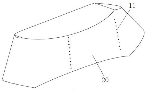
[0056] As a preferred technical solution, it also includes a guide rail 10, the guide rail 10 is provided with a through hole 11 matched with the protruding structure 8, and the protruding structure 8 passes through the guide rail 10 along the through hole 11.

[0057] The guide rail 10 acts as a limiter for the protruding structure 8, which is beneficial to prevent the protruding structure 8 from rotating, thereby restricting the protruding structure 8 from rotating and realizing linear motion, thereby improving the stability and reliability of the vortex generator.

[0058] As a preferred technical solution, it also includes mounting seats 12 connected to both ends of the guide rail 10 .

[0059] The mounting seat 12 plays a role of limitin...

Embodiment 3

[0063] Such as Figure 1 to Figure 3 As shown, as a further optimization of Embodiment 1 and Embodiment 2, this embodiment includes all the technical features of Embodiment 1 and Embodiment 2, and this embodiment provides a propeller hub.

[0064] A propeller hub includes the telescopic vortex generator described above.

[0065] Because the propeller hub adopts the above-mentioned telescopic vortex generator. During work, the driving device 6 drives the pivot 1 to make a circular motion on a plane perpendicular to the center line of the pivot 1 axis, and the pivot 1 drives the rotating connecting block 4 to move, and now the rotating connecting block 4 has a function along the axis of the pivot 1. The rotational movement of the plane perpendicular to the center line also has a linear telescopic movement away from or close to the side of the pivot 1 (wherein, the end of the rotating connecting block 4 away from the pivot makes a linear motion, and the end of the rotating conne...


PUM


Abstract

The invention discloses a telescopic vortex generator and a propeller hub formed by the same. The telescopic vortex generator comprises a pivot, a rotary connecting block, a connecting rod, a driving device, a connecting rod base and a protruding structure, the pivot is connected with the driving device, and the driving device is used for driving the pivot to do circular motion on the plane orthogonal to the center line of the pivot shaft; the pivot is connected with the rotary connecting block, the rotary connecting block is rotationally connected with the connecting rod, the connecting rod is connected with the connecting rod seat, the connecting rod seat is connected with the convex structure, and the convex structure can penetrate through an intermediate shaft fairing of the propeller hub. The problems that in the prior art, loading and unloading are troublesome, adjustment is difficult, operability is poor, and adaptability is poor are solved.

Description

technical field [0001] The invention relates to the technical field of fluid flow control, in particular to a telescopic vortex generator and a propeller hub formed therefrom. Background technique [0002] At present, the height of the hub of the coaxial rigid rotor high-speed helicopter is higher and the shape is more complex ( figure 1 ), which is more seriously affected by the rotor wake and the separation flow behind the rotor shaft, and the resistance usually accounts for about 50% of the total aircraft resistance. Take the flight test of the American XH-59 demonstration aircraft as an example. The helicopter will use 45% of the power of the whole machine to overcome the resistance of the hub. Therefore, large hub resistance is an important factor that limits the maximum flight speed and range of coaxial rigid rotor high-speed helicopters. In order to achieve high-speed flight, the key problem of huge coaxial rigid rotor hub resistance must be solved. [0003] Passive...

Claims


Application Information

Patent Timeline
Patent Type & Authority Applications(China)
IPC IPC(8): B64C11/14B64C23/06
CPCB64C11/14B64C23/06Y02T50/10
Inventor 何龙王亮权杨仕鹏李丹徐栋霞唐敏靳秋硕赵宇周畅祎白云卯
Owner LOW SPEED AERODYNAMIC INST OF CHINESE AERODYNAMIC RES & DEV CENT
Why Eureka
Try Eureka