
Automatic engine flywheel bolt tightening device

An automatic tightening device and engine technology, which is applied in metal processing, metal processing equipment, manufacturing tools, etc., can solve the problems of on-site production efficiency and engine quality, and cannot guarantee the reliability of bolt tightening, so as to reduce the labor intensity of workers and shorten the production time. Working time and improvement of working efficiency

Pending Publication Date: 2021-12-28
SHENYANG SIASUN ROBOT & AUTOMATION
View PDF7 Cites 0 Cited by
  • Summary
  • Abstract
  • Description
  • Claims
  • Application Information

AI Technical Summary

Problems solved by technology

[0002] With the continuous development and improvement of engine assembly operation automation technology, the automatic tightening engine flywheel bolt technology has been applied in the field. However, due to the wide variety of engine flywheel specifications, during the automatic tightening operation of flywheel bolts, it is necessary to replace different specifications for different flywheel models. The flywheel tightening tool is used, while the existing tightening device manually configures the position of the tightening shaft. Replacing tooling with different specifications cannot guarantee the reliability of bolt tightening, which has a great impact on on-site production efficiency and engine quality.

Method used


Image

  • Automatic engine flywheel bolt tightening device
  • Automatic engine flywheel bolt tightening device
  • Automatic engine flywheel bolt tightening device

Examples


Embodiment Construction

[0024] The present invention will be described in further detail below in conjunction with the accompanying drawings.

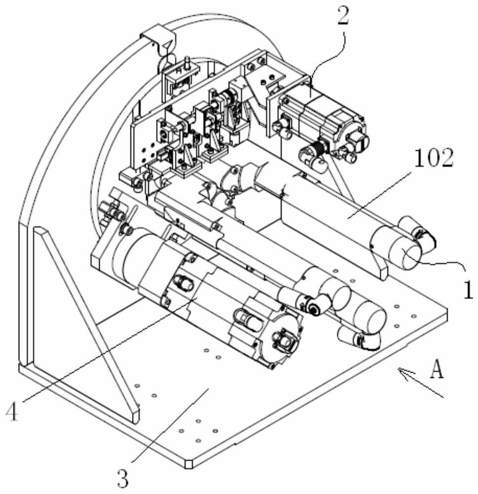
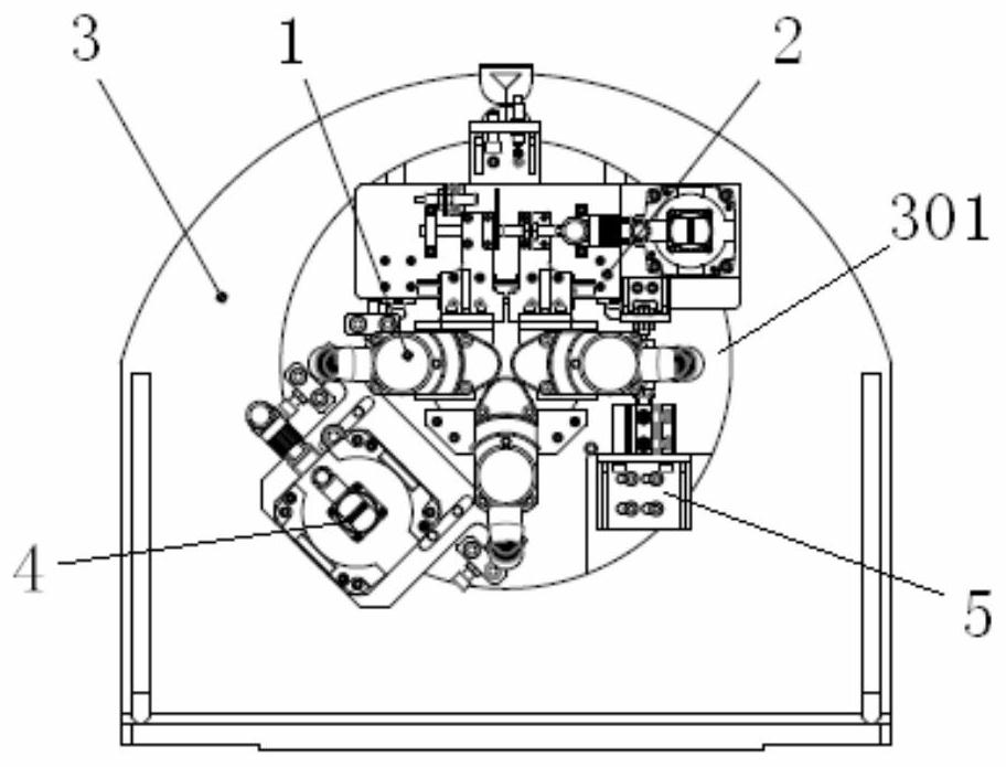
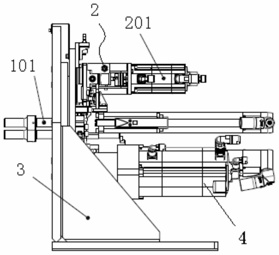
[0025] Such as Figure 1-8 As shown, the present invention includes an installation base 3, a horizontal adjustment mechanism 2, a vertical adjustment mechanism 5 and a rotary drive mechanism 4, the installation base 3 is provided with a support plate 301, the horizontal adjustment mechanism 2, the vertical adjustment mechanism 5, the rotation The driving mechanism 4 and the tightening shaft 1 are both arranged on the support plate 301, wherein the horizontal adjustment mechanism 2 includes a horizontal servo motor 201, a transmission assembly and a moving seat 204, and the two moving seats 204 are driven in reverse by the horizontal servo motor 201. move, and the horizontal servo motor 201 transmits torque through the transmission assembly, each moving seat 204 is provided with a profiling plate 2041 on the lower side, and the supporting plate 301 is provide...


PUM


Abstract

The invention relates to the field of automatic engine assembly, in particular to an automatic engine flywheel bolt tightening device which comprises a mounting base, a horizontal adjusting mechanism, a vertical adjusting mechanism and a rotary driving mechanism, the horizontal adjusting mechanism comprises a horizontal servo motor, a transmission assembly and moving seats, and the two moving seats move in opposite directions; a profiling plate is arranged on the lower side of each moving seat, a tightening shaft lower supporting plate is arranged on the mounting base, a tightening shaft hole is formed between each profiling plate and the corresponding tightening shaft lower supporting plate, a vertical adjusting mechanism and a rotary driving mechanism are arranged on the two sides of the tightening shaft hole respectively, and the vertical adjusting mechanism comprises an air cylinder and a pressing seat; and the rotary driving mechanism comprises a rotation servo motor, a rotation transmission assembly and a rotation support, the rotation support is driven by the rotation servo motor to rotate, and the tightening shaft is driven by the rotation support to rotate. The engine flywheel bolt tightening device can adapt to automatic tightening of engine flywheel bolts of various models, the influence caused by manual replacement of a tightening tool can be reduced, the operation time is shortened, and the operation efficiency is improved.

Description

technical field [0001] The invention relates to the field of automatic assembly of engines, in particular to an automatic tightening device for engine flywheel bolts. Background technique [0002] With the continuous development and improvement of engine assembly operation automation technology, the automatic tightening engine flywheel bolt technology has been applied in the field. However, due to the wide variety of engine flywheel specifications, during the automatic tightening operation of flywheel bolts, it is necessary to replace different specifications for different flywheel models. The flywheel tightening tool, while the existing tightening device manually configures the position of the tightening shaft, the replacement of tooling with different specifications cannot guarantee the reliability of bolt tightening, which has a great impact on on-site production efficiency and engine quality. Contents of the invention [0003] The purpose of the present invention is to...

Claims


Application Information

Patent Timeline
IPC IPC(8): B23P19/06
CPCB23P19/06Y02E60/16
Inventor 孙义田黎阳杨世忠勾旭东
Owner SHENYANG SIASUN ROBOT & AUTOMATION
Learn More